 The practical implementation of the project has been conceived as a dual web application that
can work as a 3D viewer widget or as a free light 3D CAD tool providing
the adequate environment for the project. This CAD tool incorporates a special
design assistant
capable of extracting conceptual geometries from pictures or sketches
provided by the user as input thanks to innovative AI algorithms.
Additionally LAI4D tries to reduce the inherent complexity of professional design tools which,
despite being suitable for experienced users, are almost unreachable
for other people not trained in the usage of CAD systems and only in
need of an occasional use. The selected implementation approach not only
allows the users an easy access to the tool, but is also an excellent
mean to build a community of designers that will provide the
necessary feedback for the system in order to make it bigger and
smarter. Start creating 3D models with the LAI4D designer.
|
FEATURES OF THE FREE WIDGET
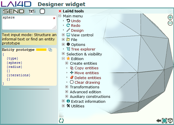
 The LAI4D widget is a minimalist 3D viewer and designer for the web,
all
in one, and is used as a test-bed for
the research. This widget can be easily embedded in other web pages in
the
form of an IFRAME element whose URL indicates the drawing source. The
viewer allows to render and explore 3D drawings in web pages without the
need of plugins even if the device is not WebGL enabled. The designer
is the free drawing tool for the people without the time to learn the usage
of a
professional CAD application and that need results in minutes. It allows
to create 3D drawings by writing the description of the
geometries using a really simple language.
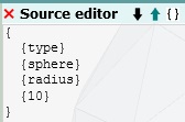
 As opposed to most modern
applications, direct source edition as plain text takes again relevance
in LAI4D because it is straightforward for occasional and inexperienced
users requiring a minimum learning effort.
At the same time, the created drawings can be shared through the
Internet uploading them to the LAI4D server from the own designer
widget. And if a more advanced usage is
required, a rich command and graphic interface is also available. As opposed to most modern
applications, direct source edition as plain text takes again relevance
in LAI4D because it is straightforward for occasional and inexperienced
users requiring a minimum learning effort.
At the same time, the created drawings can be shared through the
Internet uploading them to the LAI4D server from the own designer
widget. And if a more advanced usage is
required, a rich command and graphic interface is also available.
Although LAI4D has not been conceived as a
professional CAD tool, it can handle any kind of design since it offers
the following elements:
- Polygonal lines and polyhedrons.
- Spheres, cones and revolved surfaces.
- Curved lines, pipes, organic surfaces and meshes.
- Signals with texts and images.
- Algorithmic shapes.
- Molecular structures.
Additionally LAI4D offers other interesting features such as:
- Lai4dCL which is one of the simplest text based drawing formats, and much more comfortable than XML based formats.
- The inheritance strategy that
allows to easily define an entity or part of an entity from another one.
- The use of sub-drawings logically contained in an entity making the drawing to work much
the same as a navigable tree of folders.
- The possibility of attaching hyperlinks or custom user data to any entity of the drawing.
- The algorithmic generation of entities requiring only
JavaScript knowledge from the user.
- A free online storage service that allows the immediate sharing of the created drawings through the Internet in case the user doesn't have his own web space.
- The control of entities, view configuration or behavior options through URL instructions.
- Import and export capabilities for other drawing formats.
- A 3D sketch interpreter that uses AI to conceptualize hand-made drawings.
|
 All graphic functions of LAI4D are based
on the capabilities of the
canvas HTML element. Although major web
browsers are WebGL enabled, in case of need LAI4D can work both with WebGL and canvas 2D
rendering contexts. Obviously the
performance when using canvas 2D is
less than that when using WebGL
(accelerated graphics hardware) but, at least, it allows to handle 3D
geometries in any device.
LAI4D can be used not only online but also offline.
The LAI4D web page downloaded from the Internet can be saved to a local
drive of the client's machine using the standard "Save as" function of
the web browser normally located in the "File" menu. This will allow the
user to work offline regardless of whether the LAI4D page has been cached or not
by the browser. This is particularly necessary if the user wants to
create a distributable HTML document containing embedded LAI4D drawings
as IFRAME elements that can be displayed both online from the Internet
or offline from the local drive of a computer.
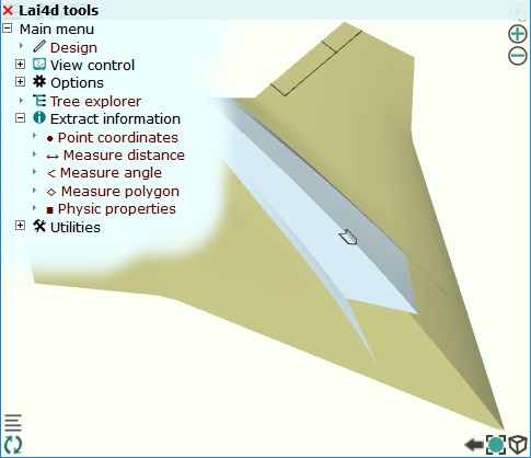
The user interface is structured
in order to allow an easy access to the functions. The most common
functions are grouped at the corners of the viewport while the rest of
functions and configurations are organized in a tree view control.
The detailed functionalities of LAI4D can be found in the reference manual at the documentation section.
|
RESEARCH
We taught the machines to understand our speech.
We taught the machines to understand our writing.
And now we are teaching the machines to understand our spatial ideas
 Designers spend an important part of their work time transferring
decisions to the design tool. This is normally done by means of commands
configured with coordinates or other parameters.
The design assistant available in the designer widget is an
experimental tool intended to provide a new way of communication between
the user and the design application. Its goal could be explained as the
capability of understanding the user ideas. When the assistant analyzes
a user's input, what it is essentially doing is
trying to understand that input in order to generate a canonical or
formal response ready to be exploited for design purposes. The tool can
be basically used in
two ways:
- Entering a text string in order to be parsed obtaining the
corresponding formal data structure, or in order to find help about a
topic.
- Making a sketch or uploading a picture in order to obtain
the corresponding conceptual geometry after a heuristic interpretation
process.
|
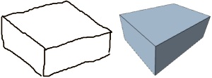 The sketch interpreter of the design assistant is the face of the conceptualizer program JAIC. The goal of this program is to "imagine" the conceptual
geometry represented by an imprecise raster image in a probabilistic way
regardless of whether it is a recognizable shape or not.
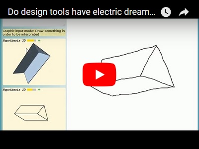
The sample image shows a set of irregular strokes at the left side, and
it is what it is, a sketch with irregular strokes. Despite their
imprecision, a person could also say that the strokes represent a
box, like the one at the right side. The necessary process to reach to
the conclusion that those irregular strokes are representing a
perspective view of a box is a conceptualization process. While a
box is a well-known shape, the conceptualization can also be extended
to the comprehension of non-recognizable and never-seen-before
geometries when such geometries have some kind of sense. The sketch interpreter of the design assistant is the face of the conceptualizer program JAIC. The goal of this program is to "imagine" the conceptual
geometry represented by an imprecise raster image in a probabilistic way
regardless of whether it is a recognizable shape or not.
The sample image shows a set of irregular strokes at the left side, and
it is what it is, a sketch with irregular strokes. Despite their
imprecision, a person could also say that the strokes represent a
box, like the one at the right side. The necessary process to reach to
the conclusion that those irregular strokes are representing a
perspective view of a box is a conceptualization process. While a
box is a well-known shape, the conceptualization can also be extended
to the comprehension of non-recognizable and never-seen-before
geometries when such geometries have some kind of sense.
JAIC only uses recognition for the OCR function. Convolutional neural
networks are very good for finding similarities between an input and a
database of patterns, like in the OCR, but this approach is not enough
to solve the problem of conceptualizing generic images. Although humans
count with biological 3D sensors like stereographic view
and ocular focus, much of the image interpretation is achieved through
conceptualization. Indeed when a human watches TV or plays a computer
simulation game or remotely pilots a vehicle through a screen, is the
conceptual vision the only mechanism in charge of building the 3D scenes
on his mind because no other 3D
information is actually available. The
LAI4D research is an indirect approach
to the understanding of the human
conceptual vision which probably is one
of the key pieces for an
enhanced motor dexterity of autonomous
robots and higher cognitive capabilities like artificial imagination.
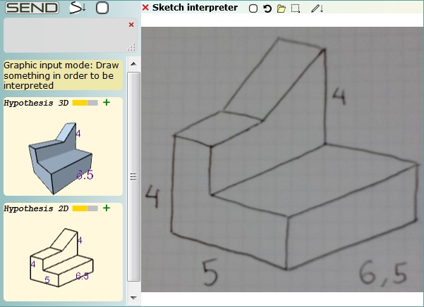 JAIC is progressively implementing the necessary knowledge to try to
understand the 2D or 3D
conceptual geometry represented by sketch images under
certain conditions. When the analysis is successful the program
generates the
corresponding canonical geometric
entities offering the possibility of adding them to the drawing.
Although the current capabilities of JAIC are still very limited its
potential is great. JAIC is progressively implementing the necessary knowledge to try to
understand the 2D or 3D
conceptual geometry represented by sketch images under
certain conditions. When the analysis is successful the program
generates the
corresponding canonical geometric
entities offering the possibility of adding them to the drawing.
Although the current capabilities of JAIC are still very limited its
potential is great.
Traditionally humans share complex ideas through
plans, sketches or other graphic means because they are more
efficient for transmitting the huge amount of information needed
to describe such ideas. Unfortunately this strategy does not work so
efficiently when the recipient is a machine since it usually demands the
information in a canonical format. But, what if the machine were able to
understand the user's ideas? That is the path LAI4D is trying to
open by developing JAIC.
This technology is
absolutely experimental and is at a very
early stage
of development. A big effort has been
done for implementing the first
versions as a client side application
offering useful offline
capabilities, but this cannot be a long
term strategy due to the limited
power of personal computers. In the
future most of its functionality
will run on remote servers better fitted
for executing the heavy queries
and brute force algorithms involved in
artificial intelligence tasks. See the section "Working with sketches"
of the Reference manual for more details.
|
|
LINKS TO OTHER RESOURCES
Although the research carried out by LAI4D is quite singular due to the
fact of not being based on conventional deep learning, there are other
research projects or organizations pursuing similar goals. Next it is
offered a list of interesting links that can be classified under the
concepts of sketch recognition, 3D reconstruction or 3D shape retrieval, as well as others with a more general AI scope:
|
CAD EXAMPLESClick
on the image links to open the examples
in a new window. Some of them may take several seconds to render.
All details about the entities used to
compose these examples can be found in the reference manual at the documentation section.

|
Paper airplane
A very simple geometry representing a paper
airplane
It is composed of a single polynet with 4 faces.
No styles are used so default colors are applied.
|
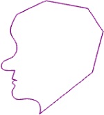 |
Face
This example composed of a single "curve" entity representing a human
face
profile demonstrates the versatility of this type of entity. If two
consecutive vertices are equal then the corresponding segment
evaluates to a single point. If two consecutive vertices are equal and
the next two consecutive vertices are also equal then a straight segment
is generated between the two pairs of vertices. Thanks to this the
"curve" entity can represent linear geometries with corners mixing
straight and curved segments.
In this case all the vertices of the curve are placed at the same plane
so it is a 2D geometry, but the "curve" entity also accepts 3D vertices.
If the vertices of a regular hexagon are used as vertices of a closed
"curve" entity, then the obtained geometry looks much like a circle.
|
 |
Pipe
The example is composed of a "pipe" entity. This type of entities are
defined by a profile and a guideline, and both can be either open or
closed. Organic surfaces may
take several seconds to render.
Profiles or guidelines
can mix curved and straight segments and can have
corners since they are
defined through the same algorithm used for the
"curve" entity. A
profile can be defined by a set of 3D points so does not need to be
planar.
The profile is assumed
to be referenced to the origin {0,0,0} and to the
orientation defined by
the Z axis. The surface is built by translating
copies of the profile
from the origin (reference point of the profile)
to the points of the
guideline and, at the same time, reorienting the
profile copy making the
reference Z axis tangent to the guideline.
Extruded surfaces can be generated using a straight segment as guideline.
|
 |
Drone
This design is an example of the use of "patch" entities. There are only
two original surfaces: one patch for the delta wing and other patch for
the air intake. The rest of surfaces are obtained by means of
symmetries from the two previous ones. Note how the border lines of the
patches can be either straight or curved lines. Organic surfaces may
take several seconds to render. Some lines have been used to decorate
the drone.
There is a hidden entity
(a tri-axis only used as reference and placed at the zone of the outlet
nozzle) with an attached
sub-drawing containing
auxiliary entities used during the design.
|
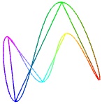 |
Curve inherited from line
This is an illustrative
example of the use of inheritance. Inherited
entities must have a
"name" member while heir entities must have an
"inherit" member
indicating the name of the entity from which to
inherit. All members of
the inherited entity will be "copied" to the
heir entity with the
exception of those already present in the heir entity which will be
preserved.
The drawing contains a
"line" entity whose name is "a" defined by 6 vertices each of which has
been assigned a color.
The drawing also
contains a "curve" entity whose definition is inherited
from that of the entity
named "a", the "line" entity, so it passes
through the same
vertices.
Note how the line is
open while the curve is closed because the curve has a member "closed"
set to a non-zero value.
|
 |
Tetrahedron with signals
This example is composed
of a single polynet that incorporates the four
available types of
signals. All the signals are anchored to the same
vertex. The polynet has a
member "link" (attaches a link) that points to
the drawing itself so,
when navigated, the same drawing is opened in a new window.
The dot signal is placed
directly over the anchored point. The polygon
signal is used as a
leading line joining the vertex and the text. The
text signal has an
offset with respect the vertex. The source of the
image signal has been
codified in Base64 instead of using its path so it is not an external
resource but an internal one.
|
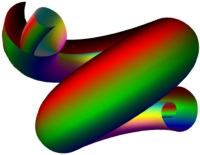 |
Spiral screw
This is an example of a "revolved" entity. By default this type of entity
builds a surface of revolution with the given profile around the Z
axis, but it can optionally be a screw like surface providing the
"advance" member, as it is done in this example.
Profiles can mix curved
and straight segments and can have
corners since they are
defined through the same algorithm used for the
"curve" entity. A
profile can be defined by a set of 3D points so it does not need to be
planar.
In this case the profile
curve represents a 3D spiral.
Cones and cylinders can be generated using a straight segment as profile.
Organic surfaces may
take several seconds to render.
|
 |
Home
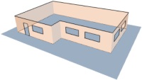
This example represents a simplified distribution of the walls of a
house. Each wall is composed of a single "face" entity, even those with
windows. The trick to build a face with holes is to consider the borders
of the holes as borders of the face. In theory, the vertices of a face
should be in the same plane but LAI4D does not perform any checking. It
simply projects the vertices and paints the corresponding polygon which
may seem strange if that set of vertices is not well constructed. The
black lines are auxiliary and can be hidden, they are not part of
the faces. One of the walls defines the wall color and the other ones
inherit it. The selected color is semitransparent.
This drawing includes a
view definition and a configuration for avoiding the camera inclination.
|
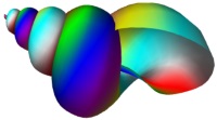 |
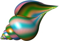
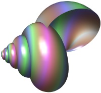
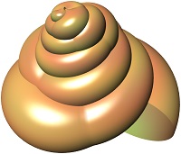
Algorithmic snail
The geometry represents a
multicolor snail shell. It has been obtained through
a program that executes
the generator
algorithm taking as
arguments the section, the number of revolutions and the colors. The
result of the
algorithm is a drawing
source with a single polynet composed of colored
faces. This source is
not very long because the surface resolution has been set to a low
value.
It is impossible for a CAD system to provide a set of predefined
entities suitable for all imaginable uses. Using a programming language
to directly generate a customized drawing source is a universal solution
to the limitations of a CAD system. LAI4D also offers a special type of
entity for this purpose: the "program" entity.
|
 |
Random city
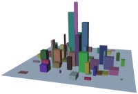
A "program" entity generates a set of "box" entities that looks like a city.
The user can provide the ground width, the ground length, the maximum
box height and the number of boxes through the "variable" member. The
greater the number of boxes is, the longer the time to render will be.
The algorithm randomly decides box sizes, positions and colors trying
to set greater box heights at the center of the ground area. Each time
the entity is rendered a new distribution is obtained due to the usage
of random functions.
As any other entity, the result of a "program" entity can be converted
into polynets using the corresponding function in the LAI4D designer.
|
 |
Molecule
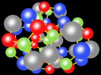
This drawing is an example of how "molecule" entities can handle a great
number of atoms efficiently from a rendering point of view. It
corresponds to a fantasy molecular structure built from four
dodecahedrons and using four atom types randomly arranged.
The atoms painted by a
"molecule" entity are not real spheres but
signals composed of
images and circular dots which notably reduces the
graphics load. In LAI4D
molecules can also show the atom symbols and each atom can have
either default color and
radius or customized ones. The color of the
atom links is also
configurable. The background color has been made black in order to
obtain a better contrast.
|
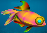 |
Fish
In this case the link
opens an HTML page with the LAI4D widget embedded in an IFRAME, instead
of showing directly
the widget's page. The
parent page defines a background image which can
be seen because the
widget is transparent. The model represents a fancy
fish composed of colored
patches, spheres, filled curves and
symmetries. Inheritance
is also used.
When a linear entity like a "curve" defines the member "fill" with a
non-zero value, it is represented as a face. This strategy is used for
some of the fish's fins.
|
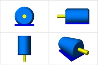 |
Multi-view device
The link opens an HTML page showing 4 views of a device. The HTML page
contains a table with 4 cells. Each cell contains a LAI4D widget
embedded in an IFRAME with a customized URL.
The URL start-up instructions of all the IFRAME elements point to the
same file which defines the device's model. In return, the different
view configurations used for each widget are passed using the member
"view" of the start-up instructions.
|
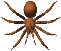 |
Spider
The geometry of this
spider with ant head has been imported from a .PLY file found at:
http://people.sc.fsu.edu/~jburkardt/data/ply/ply.html (Greg Turk)
Once imported, a color and a curved face effect has been applied.
The currently supported
import and export capabilities are covered by the functions under the
"File" menu of the LAI4D designer.
|
 |
Trumpet
The geometry of this trumpet has been imported from a .OBJ file found at:
http://people.sc.fsu.edu/~jburkardt/data/obj/obj.html
Once imported, a color and a curved face effect has been applied.
The currently supported
import and export capabilities are covered by the functions under the
"File" menu of the LAI4D designer. |
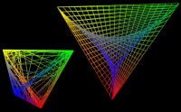 |
Interpolated tetrahedrons
Two similar "program"
entities generate artistic representations of tetrahedrons using the
function "AppLai4d.GInterpolate".
The algorithms draw lines joining the segments of the tetrahedrons using
simple linear interpolation to get the line points and point colors. One of the
algorithms distribute the lines regularly while the other one makes it randomly.
|
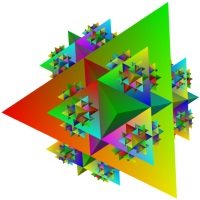 |
Fractal fantasy 1
A "program" entity that
generates a 3D fractal geometry composed of regular tetrahedrons.
In each iteration a new
tetrahedron is placed at each free face of the
tetrahedrons created in
the previous iteration. The three vertices of
the contact face of a
new tetrahedron are obtained by linear
interpolation from each
of the three edges of the contact face of the
old tetrahedron. An
optional list of colors can be distributed among the resulting vertices.
The number of iterations, the interpolation parameter and the optional
list of colors can be configured through the "variable" member.
This entity is another example of the usage of several functions
provided by the JS object "AppLai4d" for designing algorithmic entities.
|
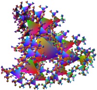 |
Fractal fantasy 2
Another example of
"program" entity generating a 3D fractal geometry composed of regular
tetrahedrons.
In each iteration a new tetrahedron is placed at certain distance of
each vertex of the tetrahedrons created in the previous iteration. The
new tetrahedrons are scaled and rotated. An optional list of colors can
be distributed among the resulting vertices.
The number of
iterations, the distance factor, the scale factor, the angle and the
optional
list of colors can be
configured through the "variable" member.
In this case the functions
provided by the JS object "AppLai4d" have been used in the optimized way
minimizing the number of arrays to be created in each operation.
|
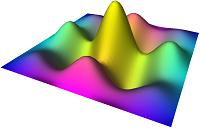 |
Simple 3D math
This example shows how
easy is to obtain the 3D representation of a "z=F(x,y)" function using a
"program" entity.
In this case the algorithm returns a "mesh" entity whose "table" member
is convenient for arranging the data generated by this kind of functions.
A set of vertex colors are calculated for artistic purposes.
|
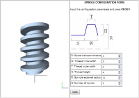 |
Configurable spindle
The link opens an HTML
page showing an IFRAME at the left and a web form
at the right. The form
allows to configure several parameters which
define the geometry of a
mechanic spindle. The button "REGEN" takes all
parameters and generates
a new URL for the IFRAME in order to paint the expected spindle.
The URL start-up
instructions of the IFRAME always points to the same file which contains
a very
simple "program" entity.
Its algorithm needs a set of variables also passed through the start-up
instructions. This is a good
example of how the
"append" member of the start-up instructions can be
combined with
inheritance to get a drawing configurable via URL.
|
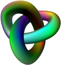 |
Knot mesh
This shape is a "mesh" entity. A mesh is a simple tabulated surface
based on
an array of vertices. Thanks to the optional member "smooth" the surface
can be curve instead of polyhedral. Furthermore the surface can be
defined as closed by the rows or the columns. This entity type is
convenient for building irregular surfaces from arrays of points or
organic surfaces based on frames.
The table of vertices of this example have been extracted from a "pipe"
entity defined by a profile and a guideline. This original pipe entity,
with almost the same geometry, can be found navigating into the children
of the mesh.
|
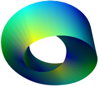 |
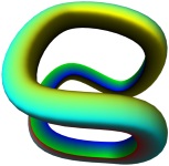
Illusion ring
The shown geometry is built up with a single tape obtained from a "mesh" entity.
It could be explained as a closed pipe in which the section is a
triangle that rotates 120° along the guideline over its own plane. The
tape takes 3 complete rounds ending at the same point where it begins so
it is closed.
Navigate into the
children of the entity to see the auxiliary constructions used to design
it.
|
 |
Bitten apple
This model has been obtained as the result of intersecting two revolved
entities, one representing an apple and the other one a bit.
The stem is a pipe entity.
Navigate into the
children of the stem to see the auxiliary constructions used to design
it.
Organic surfaces may
take several seconds to render.
|
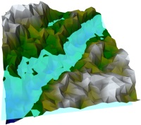 |
Terrain generator
A "program" entity is designed to generate a terrain piece with colored
mountains and a water plane using a very simple pseudo-random algorithm.
The "variable" member allows to decide the ground side, the maximum
height, the density of the mesh, the possibility of making it smooth and
the color list that will be interpolated according to the heights.
Always the drawing is regenerated a new terrain is obtained due to the
usage of random functions. Open it in design mode in order to modify the
"variable" member.
|
|
DOCUMENTATION
► Beginner's tutorial: This
tutorial is the recommended introduction for all persons new to LAI4D.
It is intended to teach the basics of design in 20 minutes. It shows
step by step how to create a simple 3D geometry from the idea up to the
publishing of the drawing on the Internet using the easiest tools.
Thanks to this exercise the user will
understand the working philosophy
of LAI4D, will be able to generate
polyhedral surfaces and polygonal
lines with colors, and will learn to
share designs online. The created geometry can be inspected in the link:
cubicle_sample.
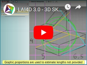
► How to design a 3D model with LAI4D: This video-tutorial
covers the designing of a 3D model using different strategies as well
as its later saving to share it online. It is based on the Beginner's tutorial of the LAI4D designer but extended in order to show also how the user can work with the menu of commands or the sketch interpreter.
► UI quick help:
This help document summarizes the functions available through the user's interface of the
viewer widget.
► Reference manual:
This document is the most complete guide to the functions of the LAI4D
widget but it is not a tutorial. It is indicated for people willing to
make a deeper usage of the tool. The following topics are covered by
the reference manual:
- Lai4dCL. The language used for describing the source of
LAI4D drawings and other data structures. Syntax, inheritance strategy,
entity model, sub-drawings...
- The standard and the extended
entity sets. It explains the
structure and properties of the
different entity types available to compose
LAI4D drawings. Polynets, lines,
surfaces, transformations, algorithmic entities, molecules, view
definitions...
- User interface. This section explains the usage of the functions
available through the LAI4D's UI. View control, file management,
configurable options, edition and query operations, design
assistant...
- Publishing LAI4D drawings. Sharing of drawings, configuring start-up instructions through the URL, offline usage...
- LAI4D architecture. Additional information for achieving a better understanding of the LAI4D functions and limitations.
Find more interesting tutorials and articles in the community.
|
FAQ
 What can I do with LAI4D? What can I do with LAI4D?
|
LAI4D
widgets
allow to render, explore and
edit 3D
drawings in
web pages without the need of plugins. The designs
can contain
lines,
surfaces, texts, images... The drawings can be
edited
through
graphic commands, as plain text using an intuitive language, or
using the design
assistant. Additionally
LAI4D
implements an amazingly simple strategy for generating algorithmic
entities. Furthermore,
the created drawings can be immediately shared through the Internet
uploading them to the LAI4D server from the own widget.
|
 Where do I start? Where do I start?
|
Visit the documentation section.
There you will find tutorials and reference manuals. The "Beginner's
tutorial" is designed to learn in 20
minutes how to create a basic 3D design
from the idea up to the publishing of the drawing on the Internet.
|
 Is LAI4D free?
|
Yes.
The standard LAI4D widget, both viewer
and
designer, can be used for free as is without modifications. It can
even be
downloaded and used offline if necessary. The function for
storing
drawings in the LAI4D server is also free and no registration is
required.
|
 Is LAI4D open source? Is LAI4D open source?
|
Not
currently,
although
this
option is
not
discarded
for the LAI4D project in the future.
LAI4D has
been built
from scratch
over the Iquix framework.
Neither the
rendering
engine nor
the design application nor the
intelligent
assistant
use external
libraries or components.
Iquix is a
proprietary
JavaScript
library that ranges 3D vector
graphics,
computational geometry, physical simulation, artificial
intelligence, multi-thread execution as well as other more conventional
functionalities.
|
 Could the LAI4D widget be customized? Could the LAI4D widget be customized?
|
Lai4d Systems can customize the LAI4D widget changing aspect, functions and behavior
according to the client requirements. Contact Lai4d Systems for more
information about this possibility.
|
 Is there any API for exploiting the LAI4D functions programmatically? Is there any API for exploiting the LAI4D functions programmatically?
|
The LAI4D widget allows the passage
of start-up instructions through the URL, see the "Widget
initialization" section of the Reference manual
for more
details. Although it is not an API,
LAI4D
implements
an
entity type
called
"program" that allows the algorithmic generation of
graphic
entities
through JavaScript programming. A public JavaScript API could
be released
in future
versions of LAI4D.
Lai4d Systems
can provide
consulting
and development services for customizing or integrating the LAI4D
functionality in other software.
|
 Can the LAI4D widget work with other drawing formats? Can the LAI4D widget work with other drawing formats?
|
The currently supported import and export capabilities are covered by the functions under the "File" menu of the LAI4D designer.
|
 How can I send error reports, suggestions or queries to the LAI4D team? How can I send error reports, suggestions or queries to the LAI4D team?
|
User participation is centralized through the LAI4D's community. Error reports, suggestions or general queries can be posted
there where members of the LAI4D team or other users will reply
a.s.a.p.
|
 How can I embed a LAI4D drawing in my web page? How can I embed a LAI4D drawing in my web page?
|
Once
you have a design ready for publishing
you will
only need to save it to the free online LAI4D storage service,
and then to
insert in your page the right HTML code for the IFRAME
element that
will show the drawing. In order to save the design use the
command
"Save server file" under the "File" menu. The simplest way to
obtain the
IFRAME code is to use the "Share" button at the top-left
corner of
the widget.
Alternatively you can also store a drawing file in your own web space
and instruct
the widget
to open it
directly from there using its
absolute
URL. A more
detailed
explanation can be found in the
section
"Publishing
LAI4D
drawings" of the Reference manual.
|
 What is a polynet? What is a polynet?
|
It
is the intrinsic graphic entity of LAI4D. A
polynet
defines a set of vertices, a set of faces, a set of lines and
other
properties for colors or line widths for example. Any other
type of
graphic entity is to be converted into a polynet or a set of
polynets
during the interpretation process before it can be rendered.
|
 How can I include texts and images in a drawing? How can I include texts and images in a drawing?
|
This
is done through "signals" that must be
integrated
in a polynet entity. Signals are 2D graphic entities that are
always
painted parallel to the projection plane regardless of the
camera
orientation. They can be images, texts, circular dots and
polygons.
Each signal is anchored to a vertex of the polynet so it has a
3D position.
|
 Why is so easy to use algorithmic entities? Why is so easy to use algorithmic entities?
|
What
a "program" entity does is essentially
to execute a
JS algorithm that returns a standard LAI4D entity that
can then be
rendered in the usual way. The Lai4dCL syntax is so simple that the
source of a
LAI4D entity
can be immediately represented as a JS array or vice
versa.
Thanks to this characteristic the result of the "program" entity
can directly
be a JS array instead of a Lai4dCL structure so there is no
need to deal
with specific APIs to generate algorithmic entities. This
advantage
combined with the fact the LAI4D entities have a very
intuitive
format make "program" entities really easy to use.
|
 How does the LAI4D widget exploit artificial intelligence? How does the LAI4D widget exploit artificial intelligence?
|
The use of AI is centered in the design
assistant.
Its sketch
interpreter is an experimental tool able to
extract the
conceptual
3D geometry represented by the given sketch (hand-drawn or
loaded from
an image file). The
result can
be later
edited in the model space as a normal entity.
|
 Which is the difference between shape recognition and shape conceptualization? Which is the difference between shape recognition and shape conceptualization?
|
A
shape recognition process attempts to find a match for the analyzed
image (or other input)
within a
shape descriptions data base returning as result the found
record if
any. However, a shape conceptualization process attempts to
"imagine"
the shape represented by the analyzed image regardless of
whether it
is a recognizable shape or an abstract one returning the
imagined
shape's geometry as result.
|
 How can I get involved in the project? How can I get involved in the project?
|
The easiest way to get involved is to become an expert user in order to participate in the community helping other users, writing tutorials and providing feedback to the LAI4D development team.
|
|
RELEASE NOTES
3.5.20221229
Improvements and new functions developed in the Iquix framework for the project GENEVL.
 Older versions Older versions
|
3.4.20201213
The estimation of hidden faces has been improved.
The brightness calculation scheme has been upgraded including a new
factor "focus reflection factor" indicating the proportion of reflected
directional light that is focused instead of diffuse.
A "copy to clipboard" button has been included within the information
elements of the commands: "Point coordinates", "Measure distance",
"Measure angle", "Measure polygon", "Physic properties".
The command "Create extruded surface" has been replaced by the command
"Create pipe". An extruded surface can be created entering a straight
segment as guideline of the pipe.
Other minor improvements. |
3.3.20200105
The manual input of polar coordinates has been enabled through the new
button (<) in the input area.
The command "Transform entities" has been enhanced making only the first
pair of points mandatory. Depending on the number of pairs of points
provided the operation can be: simple translation, translation +
rotation +
elongation along a line, translation + plane alignment + planar
deformation, translation + complete transformation.
The prototype of the entity "transformation" has been modified in order
to resemble the behavior of the command "Transform entities". Now the
transformation is defined through the member "pairs" which can hold up
to four pairs of points. The old behavior using the members "matrix",
"origin" and "move" was of little use since any entity can declare the
members "transform" and "translate". This new prototype can be
particularly useful for creating algorithmic entities.
The function for pausing the command has been also implemented for the
selection of entities. If used then the current command is paused and
the user can change the camera configuration in the usual way.
In the sketch interpreter, the interpretation of holes sketched in faces
has been improved. In order to be correctly handled, the loops
corresponding to the holes must be connected to the external contour of
the face. The resizing of faces with holes and assigned measures has
been improved. See the section "Working with sketches" of the Reference manual for more details.
|
3.2.20190705
The "dynamic zoom" navigation has been implemented. Each mouse wheel
event produces a combination of a zoom increment plus a camera movement.
To use the dynamic zoom is a comfortable way of exploring a wide
scenario without the need of calling several times to different camera
configuration buttons.
Now the sketch interpreter allows the loading of pictures into the
sketch area through drag & drop operations.
Now the designer widget allows the loading of drawing files into the
canvas area through drag & drop operations.
The text resolution in WebGL contexts has been increased.
|
3.1.20190402
The performance of several CAD commands has been improved.
Assignment of measures to segments improved.
The configuration "Inverse depth interpretation" has been added to the
sub-menu "Design assistant options". By checking this option the design
assistant changes the depth interpretation criterion when generating 3D
hypothesis.
Now the design assistant tries to find the evident reference system of
the 3D hypotheses when passing them to the model space. If found then
the hypotheses are reoriented before placing the new geometry at the
model space.
The new command "Cut by plane" calculates the line and surface
fragments resulting from the intersection of a set of entities and a
plane defined by 3 points.
|
3.0.20190101
Several improvements in the sketch interpreter.
Imagination of hidden faces improved. Now this function can work with
more complex scenarios.
Interpretation of cyclic geometries improved. Now the conceptualization
of regular polygons or stars is easier.
Assignment of measures to segments improved. Now the algorithm for
assigning drawn measures to the segments is smarter.
Improved the algorithm for resizing the segments without assigned
measure when there are other segments with assigned measure.
Fixed a problem in the patch entity when the sides have double points.
Sphere entity generation optimized.
|
2.4.20180929
The "Color generator" tool has a new button for clearing the color
selection.
The new command "Project to 2D" replaces the selected entities by
polynets with the corresponding 2D projection in camera coordinates.
The new command "Solve triangle" calculates the side lengths and angles
not provided of a triangle and passes it to the design space.
The new command "Solve tetrahedron" calculates the vertices of a
tetrahedron from the set of segment lengths and passes it to the design
space.
Minor changes in the sketch interpreter.
|
2.3.20180718
Implemented import/export capability to ".stl" format.
The new command "General intersection" calculates the line and surface
fragments resulting from the intersection of a set of entities. This new
command includes the functionality of the old command "Line
intersections" that has been removed.
The new command "Cut-line between surfaces" returns the cut-line
resulting from the intersection of a set of surface entities.
The "Browser's storage tool" includes now an "Overwrite" button for each
record.
A
new command "Generate surface contour" returns the bounding contour of
the selected surfaces.
|
2.2.20180403
Several improvements in the sketch interpreter.
Some of the initial stages of the sketch interpretation have been
modified in order to make the analysis more image-size independent. The
previous versions had many threshold values correctly calibrated for
small images but not adequate for larger images.
The new command "Copy properties" allows to copy the configured members
from the selected source entity to the selected set of target entities.
A
new command "Focus entity set" allows to focus the view on the selected
set of entities.
The node items shown in the 'Tree explorer' tool includes now a button
to focus the view on the rendered entity owning the node.
|
2.1.20180206
Several improvements in the sketch interpreter.
OCR function improved.
Imagination of hidden faces improved.
A
new command "Line intersections" calculates the line fragments
resulting from the intersection of several 3D linear entities.
A
set of commands for creating regular polyhedrons have been implemented.
|
2.0.20180113
A
light OCR (Optical Character Recognition) functionality for recognizing
drawn measures has been implemented
in the sketch interpreter. Now the user can optionally provide measures
to some of the sketched elements in order to obtain a geometry with
specific dimensions.
A
new function for imagining hidden faces has been implemented in the
sketch interpreter.
The following configurations have been added to the sub-menu "Design
assistant options":
- Perform OCR.
- Imagine hidden faces.
- Print assigned measures.
- Print non-assigned measures.
|
1.12.20171126
The function for opening drawing files stored in external domains has
been enabled.
Several improvements in the sketch interpreter.
A
new command "Batch modify" allows to modify, remove or add members to
entities in batch mode.
The sketch interpreter implements a new button for defining a constrain
window for the sketch analysis.
A
new command for creating regular polygons has been implemented.
The new command "Set default properties" allows to change colors and
other properties to the selected entities.
The new menu item "Label as 'auxiliary'" allows to create new entities
labeled as "auxiliary".
Now the auxiliary constructions are directly created with the label
"auxiliary".
The new command "Select auxiliary entities" appends to the current
selection all entities with the label "auxiliary". After that the
auxiliary entities can be easily hidden or deleted.
The command "Properties" has been renamed to "Physic properties" and now
shows at the end the aggregated properties of the selected entities as a
compound.
|
1.11.20170917
The "mesh" entity type has been improved:
- The new members "closed s" and "closed t" allow to generate the surface closed in any or both of the two directions.
- The new member "table colors" is the convenient way to provide the colors for the set of vertices defining the geometry.
-
The new member "smooth" allows to create organic surfaces with
an
accurate control over the points by which the surface must pass.
A
new command for creating mesh entities has been implemented.
The command "Align entities" now includes the option to perform a
scaling while aligning the entities.
The "Modify vertex" command allows now to modify also "mesh" and "patch"
entities.
The WebGL 1.0 extension "OES_element_index_uint" has been enabled to
allow the rendering of geometries with a huge number of vertices.
Fixed problem in the generation algorithm of the "pipe" entity type.
|
1.10.20170701
A
new command for creating general revolved entities has been
implemented.
A
new command for creating extruded surfaces has been implemented.
A
new command for creating patch entities has been implemented.
A
new command for generating polar array distributions has been
implemented.
The on-screen point selection function has been improved.
|
1.9.20170528
A
new set of commands for creating circles and arcs has been implemented.
A
new set of commands for creating spheres has been implemented.
A
new set of commands for creating cylinders and cones has been
implemented.
Now the UI allows the on-screen selection of singular points like
centers or control points, apart from standard vertices.
The "Modify vertex" command now allows to modify also "curve" entities.
A
new function for entering relative coordinates has been implemented.
It allows to define a new point as an offset with respect the previous
entered point.
The new command "Convert to wireframe" allows to obtain the wire
representation of the selected entity.
|
1.8.20170430
A
new sub-menu "Edition options" has been created to group those general
configurable options applicable to the commands directly involved in the
edition and creation of entities.
The auxiliary constructions have been improved with new in-place
configurations.
The commands for editing drawing metadata have been improved.
New member "base" added to the "polar" entity type. If provided then the
elements are only translated and not rotated as they are copied to the
destination points of the polar array distribution.
The "Share" function offers a new configurable option to include the
current view definition in the URL start-up instructions. This allows to
share the drawing using the current view definition without modifying
the own drawing source.
Curve's algorithm optimized.
The "Plan view" command has been replaced by the collection of commands
"Predefined views".
|
1.7.20170415
The rendering context type indicator button shown in the bottom-right
corner has been replaced by the much more useful "Zoom extent" button.
The "Zoom extent" menu item of the "View control" menu has been removed.
The menu command "Purge browser's storage" has been moved to a button
within the "Browser's storage" tool.
The new command "Optimize drawing" merges all the entities of the
drawing into a reduced set of polynets in order to improve
the performance of the widget when using WebGL.
The color picker control has been improved.
|
1.6.20170405
The command "Merge entities" has a new option that allows to decide if
the signals must be preserved in the result or not.
Now the design assistant will show the last used command as a
suggestion.
The text responses of the design assistant now have a "copy to
clipboard" button.
The command "WebGL properties" has been integrated in the command
"Browser capabilities".
|
1.5.20170305
Commands for configuring default color for faces and lines in new
entities have been implemented.
A
new function for pausing a command has been implemented. If used then
the current command is paused and the
user can change the camera configuration in the usual way. This function
is typically used while selecting points in
the screen that are hidden for the current camera orientation.
New command "Create text signal" for creating polynets with text
signals.
|
1.4.20170212
The command "Create polygonal" has been replaced by the command "Create
line" for creating 'line' entities.
New command "Create face" for creating 'face' entities.
New command "Create box" for creating 'box' entities.
The "Tree explorer" component is improved by adding a button for
inspecting the parent node, and a button for inserting new nodes before
the current one.
Now the command "Copy entities" can copy the same selection to multiple
destination points.
|
1.3.20170129
The "Explode entities" command has been improved including the new
in-place configuration "create 'face' and 'line' entities instead of
polynets".
A
new command "Concatenate lines" has been implemented. It is useful for
generating a single line from a group of different connected lines.
The recognition of polyhedrons in the "design assistant" has been
improved.
|
1.2.20170101
A
progressive zoom function has been implemented for the Zoom-in and
Zoom-out buttons of the top-right corner. The progressive zoom can be
performed applying a long-press event over the buttons. The traditional
stepped zoom function is preserved.
Some vector and geometric calculation functions have been added to the
JS
object "AppLai4d" in order to enrich and facilitate the development of
algorithmic entities. See the "program" entity section in the Reference manual for more information.
|
1.1.20161204
The command "Merge Entities" allows now to decide whether to merge the
vertices or not.
Official file extension for LAI4D drawings is ".L4D".
Implemented import/export capability to ".ply" (point cloud) format.
Implemented import/export capability to ".obj" format.
New member "append" added to the URL start-up instructions. The "append"
member is intended to let the user to modify the drawing source from
the URL before it is interpreted.
Improved user interface for the creation of polygonal entities.
Icon size of on-screen controls increased.
|
1.0.20160624
Initial version. |
|
|
PARTICULAR TERMS AND CONDITIONS
See the General terms and conditions.
|

 Laboratory
of
Artificial
Intelligence
for
Design

 The LAI4D widget is a minimalist
 All graphic functions of LAI4D are based
on the capabilities of the
canvas HTML element. Although major web
browsers are WebGL enabled, in case of need LAI4D can work both with
 The
The  JAIC is progressively implementing the necessary knowledge to try to
understand the 2D or 3D
conceptual geometry represented by sketch images under
certain conditions. When the analysis is successful the program
generates the
corresponding canonical geometric
entities offering the possibility of adding them to the drawing.
Although the current capabilities of JAIC are still very limited its
potential is great.


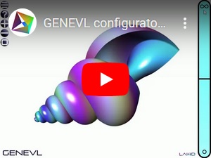
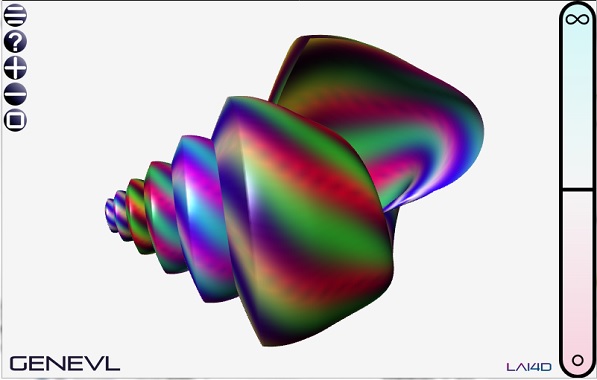

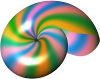

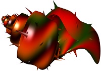
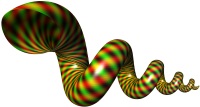
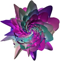


 and
then
use the function "Save configuration" in order to save a copy
of
the
configuration to your local drive. Now you can close the
browser's window displaying the nautilus if you want.