|
This
tutorial is the recommended introduction for all persons new to LAI4D.
It is intended to teach the basics of design in 20 minutes. It shows
step by step how to create a simple 3D geometry from the idea up to the
publishing of the drawing on the Internet using the easiest tools.
Thanks to this exercise the user will understand the working philosophy
of LAI4D, will be able to generate polyhedral surfaces and polygonal
lines with colors, and will learn to share designs online. For a detailed explanation of functions see the
LAI4D reference manual.
Planning

|
|

|
fig. 1
|
|
fig. 2
|
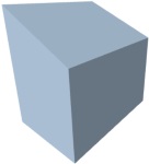
The objective is to design a small cubicle for storing tools and
materials like the one shown in the sketch of figure 1. It will have the
basic
details: four walls and an inclined ceiling. The measures are expressed
in meters although it is meaningless since LAI4D only understands
drawing units. The LAI4D designer offers several possibilities for
defining
geometries, but we are going to use direct text edition because it is
the easiest method to learn.
Whatever the method, we need the coordinates of the points
defining the geometry to be designed. The standard reference system in
LAI4D is the one shown in figure 2. The plane XY is normally used as
ground reference and the Z axis is considered vertical. We are going to
assume that the origin for coordinates is located at the corner marked
with a green circle in figure 1; we could place it wherever we want but
that is a logical position taking into account what we want to draw.
|
Once the reference system is defined, it is very easy to get, for example,
the sequence of coordinates of the four points of the cubicle's base.
Each point has three coordinates XYZ. Since the base is at the plane XY
the Z coordinate of all points will be 0:
0, 0, 0
|
2, 0, 0 |
2, 3, 0 |
0, 3, 0 |
A similar exercise will be necessary for each of the faces of the design.
|
The user interface
Now it is time to open the LAI4D designer widget.
The widget is divided in two main areas: the design assistant at
the left or bottom (which is not going to be used), and the graphic area
at the right or top that contains all necessary tools for this
tutorial. When the user moves the pointer over the graphic area (or touches
it in a touch screen device), a series of groups of controls are shown
at the corners of the graphic area. After a period without events those
controls are hidden again. Only a few functions are going to be used in
this tutorial. The most important one is the source editor which can be
activated pressing the button ( ) found at the group of controls of the bottom-left corner. ) found at the group of controls of the bottom-left corner.
Given that the user is new to LAI4D, it is advisable to follow the
instructions of this tutorial step by step in order to avoid mistakes.
But, since the used edition method is the direct source edition as plain
text, in case the user doesn't know how to fix an error then simply reload
the widget HTML page, copy the corresponding source from this document
and paste it into the widget's source editor, the work will be
restored after committing the source.
|
Defining the first face

|
| fig. 3
|
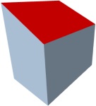
The first face to be created will be that of the plane XZ (Y = 0)
highlighted in red in figure 3. It has four points whose coordinates
are:
0, 0, 0
|
2, 0, 0 |
2, 0, 2 |
0, 0, 3 |
Since a face is a closed geometry the starting point of the sequence is
irrelevant. The sequence must follow the border of the face but the
sense of its order is neither relevant. Therefore the sequence of points
could also be:
2, 0, 0 |
0, 0, 0 |
0, 0, 3 |
2, 0, 2 |
|
In LAI4D a face can be defined
with a "face" entity. An entity is a
data structure which, at least, must indicate the type of entity ("face"
in this case). The rest of provided information depends on the type. For
"face" entities the only mandatory data is the sequence of vertices
defining the geometry, at
least three vertices are necessary. Other optional data such as the
color could be provided, but if not then a default color will be
automatically used. The text representation of this first "face" entity
in the language of LAI4D is:
{
  {type}
  {face}
  {vertices}
  {
    {{0}{0}{0}}
    {{2}{0}{0}}
    {{2}{0}{2}}
    {{0}{0}{3}}
  }
}
|
In this language each data item is enclosed by curly brackets. The items
can be simple like strings or numbers, or they can be composed of other
items like a point with several coordinates. The entity itself is a compound item. LAI4D ignores the
indentation or the text division into lines or the blanks between items. What is really
important is the content of the simple items that must not be altered.
For example this "face" entity could also be written in a single line
as:
{{type}{face}{vertices}{{{0}{0}{0}}{{2}{0}{0}}{{2}{0}{2}}{{0}{0}{3}}}}
Or in two lines as:
{{type}{face}{vertices}

{{{0}{0}{0}}{{2}{0}{0}}{{2}{0}{2}}{{0}{0}{3}}}}
Any entity is a sequence of member-value pairs. In this case there are
two members: "type" and "vertices". The order of the pairs is not
relevant so the previous "face" entity could also be written as:
{{vertices}{{{0}{0}{0}}{{2}{0}{0}}{{2}{0}{2}}{{0}{0}{3}}}{type}{face}}
Now that it is clear how to describe a "face" entity, let's define it. In the
LAI4D designer activate the source editor tool by pressing the button ()
at the group of controls of the bottom-left corner. The source editor
shows a header with several buttons, and an editable text area (empty by default) where the
drawing source can be edited as plain text. Any of the previously given
text representations of this first "face" entity is valid so copy one
of them and paste it into the text area. This action has no effects and
the new drawing source will not be interpreted by LAI4D until the commit
button ( ) is pressed, but this will be done later after defining all the
faces. ) is pressed, but this will be done later after defining all the
faces.
|
Defining the rest of the faces

|
| fig. 4
|
The faces of the cubicle are independent entities so the order in which
they are defined is not important. The next face to be created will be
that parallel to the first one
highlighted in red in figure 4. This parallel face is placed at the
plane Y = 3. The coordinates of the points are the same as those of the
first face but for the Y coordinate which is 3 instead of 0:
0, 3, 0
|
2, 3, 0 |
2, 3, 2 |
0, 3, 3 |
Assuming single line notation, the source of the drawing up to this step is:
{{type}{face}{vertices}{{{0}{0}{0}}{{2}{0}{0}}{{2}{0}{2}}{{0}{0}{3}}}}
{{type}{face}{vertices}{{{0}{3}{0}}{{2}{3}{0}}{{2}{3}{2}}{{0}{3}{3}}}}
|
|

|
| fig. 5
|
The next face to be created will be
that of plane YZ (X = 0)
highlighted in red in figure 5. The coordinates of the points are:
0, 0, 0 | 0, 0, 3 |
0, 3, 3
|
0, 3, 0
|
Assuming single line notation, the source of the drawing up to this step is:
{{type}{face}{vertices}{{{0}{0}{0}}{{2}{0}{0}}{{2}{0}{2}}{{0}{0}{3}}}}
{{type}{face}{vertices}{{{0}{3}{0}}{{2}{3}{0}}{{2}{3}{2}}{{0}{3}{3}}}}
{{type}{face}{vertices}{{{0}{0}{0}}{{0}{0}{3}}{{0}{3}{3}}{{0}{3}{0}}}}
|
|

|
| fig. 6
|
The next face to be created will be placed at the plane X = 2 parallel to the YZ
highlighted in red in figure 6. The coordinates of the points are:
2, 0, 0 | 2, 0, 2 |
2, 3, 2
|
2, 3, 0
|
Assuming single line notation, the source of the drawing up to this step is:
{{type}{face}{vertices}{{{0}{0}{0}}{{2}{0}{0}}{{2}{0}{2}}{{0}{0}{3}}}}
{{type}{face}{vertices}{{{0}{3}{0}}{{2}{3}{0}}{{2}{3}{2}}{{0}{3}{3}}}}
{{type}{face}{vertices}{{{0}{0}{0}}{{0}{0}{3}}{{0}{3}{3}}{{0}{3}{0}}}}
{{type}{face}{vertices}{{{2}{0}{0}}{{2}{0}{2}}{{2}{3}{2}}{{2}{3}{0}}}}
|
|

|
| fig. 7
|
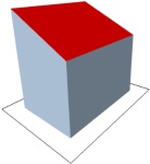
The last face is the ceiling
highlighted in red in figure 7. The coordinates of the points are:
0, 0, 3 | 0, 3, 3 |
2, 3, 2
|
2, 0, 2
|
Assuming single line notation, the source of the drawing up to this step is:
{{type}{face}{vertices}{{{0}{0}{0}}{{2}{0}{0}}{{2}{0}{2}}{{0}{0}{3}}}}
{{type}{face}{vertices}{{{0}{3}{0}}{{2}{3}{0}}{{2}{3}{2}}{{0}{3}{3}}}}
{{type}{face}{vertices}{{{0}{0}{0}}{{0}{0}{3}}{{0}{3}{3}}{{0}{3}{0}}}}
{{type}{face}{vertices}{{{2}{0}{0}}{{2}{0}{2}}{{2}{3}{2}}{{2}{3}{0}}}}
{{type}{face}{vertices}{{{0}{0}{3}}{{0}{3}{3}}{{2}{3}{2}}{{2}{0}{2}}}}
|
|
Committing changes
Once the text source of the five
faces has been typed in the text area of the source editor, it is time to
render the drawing. In order to commit the changes press the button ()
placed at the header of the source editor tool. By doing this LAI4D
will parse and interpret the new drawing source. If no problems are
found then the drawing is rendered and the source editor tool is hidden.
|
| fig. 8
|
In normal conditions the graphic area will show the geometry with a
convenient zoom. To increase or reduce the zoom press the buttons ( ) and ( ) and ( )
at the top-right corner as many times as necessary. The initial view configuration is looking from up towards down, it
is to say, the Z axis is perpendicular to the viewport. To change the
camera orientation simply drag the mouse over the graphic area holding
the left button (or drag the finger in a touch screen device). )
at the top-right corner as many times as necessary. The initial view configuration is looking from up towards down, it
is to say, the Z axis is perpendicular to the viewport. To change the
camera orientation simply drag the mouse over the graphic area holding
the left button (or drag the finger in a touch screen device).
After updating a drawing source it is a common situation to get a
rendering with an inadequate zoom or that doesn't show the entire
design on the screen. The easiest way to fix this problem is to use the
"zoom extent" button ( ) at the bottom-right corner. This function modifies the current view
configuration in order to show the full scene in the graphic area. The result should be something similar to the figure 8. ) at the bottom-right corner. This function modifies the current view
configuration in order to show the full scene in the graphic area. The result should be something similar to the figure 8.
The truth is that the commit button could have been pressed at any
moment before defining the five faces because the drawing source can be
changed as many times as desired. When manually editing a drawing
source, to make a mistake is very usual. In such a case LAI4D shows a
warning message indicating the problem found. Don't mind. Close the
warning message pressing the close button ( ) at the top-left corner of the message window; reopen the source editor; fix the error in the drawing source and commit again. ) at the top-left corner of the message window; reopen the source editor; fix the error in the drawing source and commit again.
|
Setting color
The goal is to assign a red color to the ceiling of the cubicle. Open again the source editor tool pressing the button ().
The text area shows the drawing source as it was written before. Now we
are going to modify the ceiling face definition which is the last
defined face. For assigning a color to a "face" entity a new member named
"face color" is necessary. The value of the color member is a compound
of three numbers in the range [0, 1] corresponding to the three
components of a RGB color definition (red, green, blue). Actually a
color definition can have four numbers being the last one that
corresponding to the alpha channel (opacity) but it is not used in this
tutorial.
Take the definition of the ceiling face. As mentioned before, the order
of the members in an entity definition is meaningless so the "face
color" member can be placed, for instance, at the beginning of the
entity definition. The new face definition with color in single line notation would be:
{{face color}{{1}{0}{0}}{type}{face}{vertices}{{{0}{0}{3}}{{0}{3}{3}}{{2}{3}{2}}{{2}{0}{2}}}}
|
| fig. 9
|
Therefore, the complete source of the drawing is:
{{type}{face}{vertices}{{{0}{0}{0}}{{2}{0}{0}}{{2}{0}{2}}{{0}{0}{3}}}}
{{type}{face}{vertices}{{{0}{3}{0}}{{2}{3}{0}}{{2}{3}{2}}{{0}{3}{3}}}}
{{type}{face}{vertices}{{{0}{0}{0}}{{0}{0}{3}}{{0}{3}{3}}{{0}{3}{0}}}}
{{type}{face}{vertices}{{{2}{0}{0}}{{2}{0}{2}}{{2}{3}{2}}{{2}{3}{0}}}}
{{face color}{{1}{0}{0}}{type}{face}
{vertices}{{{0}{0}{3}}{{0}{3}{3}}{{2}{3}{2}}{{2}{0}{2}}}}
|
After modifying the drawing source commit the changes by pressing the button (). The result will be something similar to that shown in figure 9.
|
Drawing lines
Now we want to draw a closed line
around the cubicle's base separated 0.5 meters. In LAI4D "line"
entities are very similar to "face" entities since the only necessary
geometric information are the vertices. At the beginning of this
tutorial we saw that the points of the base are:
0, 0, 0
|
2, 0, 0 |
2, 3, 0 |
0, 3, 0 |
Taking into account the offset of 0.5 meters the new coordinates of the line points would be:
-0.5, -0.5, 0
|
2.5, -0.5, 0 |
2.5, 3.5, 0 |
-0.5, 3.5, 0 |
As opposed to faces, lines are open geometries by default. To build a
closed line it is either necessary to provide a last point coincident
with the first one, or to provide a special member indicating that the
line is closed. Then, the closed "line" entity could be written as:
{{type}{line}{vertices}{{{-0.5}{-0.5}{0}}{{2.5}{-0.5}{0}}{{2.5}{3.5}{0}}{{-0.5}{3.5}{0}}{{-0.5}{-0.5}{0}}}}
Although the recommended approach is to use the "closed" member with a non-zero value as:
{{type}{line}{closed}{1}{vertices}{{{-0.5}{-0.5}{0}}{{2.5}{-0.5}{0}}{{2.5}{3.5}{0}}{{-0.5}{3.5}{0}}}}
|
| fig. 10
|
Therefore, the complete source of the drawing is:
{{type}{face}{vertices}{{{0}{0}{0}}{{2}{0}{0}}{{2}{0}{2}}{{0}{0}{3}}}}
{{type}{face}{vertices}{{{0}{3}{0}}{{2}{3}{0}}{{2}{3}{2}}{{0}{3}{3}}}}
{{type}{face}{vertices}{{{0}{0}{0}}{{0}{0}{3}}{{0}{3}{3}}{{0}{3}{0}}}}
{{type}{face}{vertices}{{{2}{0}{0}}{{2}{0}{2}}{{2}{3}{2}}{{2}{3}{0}}}}
{{face color}{{1}{0}{0}}{type}{face}
{vertices}{{{0}{0}{3}}{{0}{3}{3}}{{2}{3}{2}}{{2}{0}{2}}}}
{{type}{line}{closed}{1}{vertices}
{{{-0.5}{-0.5}{0}}{{2.5}{-0.5}{0}}{{2.5}{3.5}{0}}{{-0.5}{3.5}{0}}}}
|
After modifying the drawing source commit the changes by pressing the button ().
Modify the view configuration if necessary. The result will be
something similar to that shown in figure 10. The default color for
lines is black ({{0}{0}{0}}). In a similar way to that of faces, the color of a "line" entity can be specified using the member "line color".
|
Sharing the design
The easiest method to share a LAI4D drawing through the Internet consists of two steps:
- To save the drawing in the LAI4D server obtaining a reference name that will allow to retrieve it in the future.
- To configure an URL with that reference name in order to retrieve
and render the drawing when typed in the address bar of a web browser.
For saving the drawing in the LAI4D server ensure your device is
connected to the Internet. Open the tools menu by pressing the button ( )
at the top-left corner.
Press the plus button of the tree item labeled as " )
at the top-left corner.
Press the plus button of the tree item labeled as " File" which will expand the corresponding branch. Then press the
item labeled as "
Save server file". This action will show the "Save to server" tool. The
tool requests to type in the text field the intended root name of the
file. LAI4D provides by default a generated name that can be deleted.
Type the name "cubicle_sample" and then press the "Save" button. After
this, LAI4D connects to the server and tries to store the drawing file
with the provided name. When the saving process ends successfully the
server responds with the final reference name given to the file which is
the result of appending a random string to the provided name. The user
must preserve this reference name since it is the only way to retrieve
the stored drawing (using the
tool " File" which will expand the corresponding branch. Then press the
item labeled as "
Save server file". This action will show the "Save to server" tool. The
tool requests to type in the text field the intended root name of the
file. LAI4D provides by default a generated name that can be deleted.
Type the name "cubicle_sample" and then press the "Save" button. After
this, LAI4D connects to the server and tries to store the drawing file
with the provided name. When the saving process ends successfully the
server responds with the final reference name given to the file which is
the result of appending a random string to the provided name. The user
must preserve this reference name since it is the only way to retrieve
the stored drawing (using the
tool " Open server file"). The URL for sharing the file is automatically shown too. Open server file"). The URL for sharing the file is automatically shown too.
Suppose that the returned reference name is "cubicle_sample_a0k". The URL configured to
open the drawing in the LAI4D viewer widget is:
http://widget.lai4d.org/lai4d_viewer.html?{{file}{{lai4d}{cubicle_sample_a0k}}}
Notice that you can also store a drawing file in your own web space if
you have one. In this case the sharing URL would look like:
http://widget.lai4d.org/lai4d_viewer.html?{{file}{http://www.mydomain.com/cubicle_sample.txt}}
Now anyone can view the designed cubicle by typing this URL in the
address bar of any web browser connected to the Internet. By default
LAI4D performs a zoom extent when opening a drawing if it doesn't include a view definition.
|
Suggested exercises
LAI4D offers many more functions and entity types than those covered in this tutorial and they can be consulted in the LAI4D reference manual. But regarding the topics treated in this document, the user is invited to test the following experiments:
- Add the member
{stroke}{1} to any "face" entity. It indicates that the face must be rendered with its boundaries stroked.
- Add the member
{fill}{1} to any "line" entity. It indicates that the line must be rendered filled as if it were a face.
- Remove the Z coordinate of any point definition if its value is 0.
Nothing happens since LAI4D automatically completes the last omitted
coordinates of points with 0 when the drawing source is interpreted.
- Alter the name of a mandatory member like "type" or "vertices" of
an entity, or replace a number by a letter. After committing the source the interpretation partially
fails and LAI4D shows the corresponding error message. Nevertheless, LAI4D tries to
render what it can.
- Modify the coordinates of a point in order to create a non-flat
face. LAI4D triangulates and renders the face, although it may seem
strange if not well constructed.
- In the Tools menu ()
call the function "Extract information/Advanced/Show current view".
This will show an entity with the current view configuration. Copy and
append it to the source editor as another additional entity. Now the
drawing includes the view definition so, when opened in the LAI4D widget
this view configuration will be used instead of the default one.
- In the source editor tool press the button ().
This will replace the content of the text area by the current canonical
source of the drawing. The drawing source is canonical if all the
graphic entities are encapsulated in a "drawing" entity. The source
editor accepts both canonical and non-canonical sources.
- Perform a long-press over an entity in the canvas to open the contextual menu. Press the button (
 )
to open the Tree explorer. There you can edit all the properties of the
entity. You can also access the Tree explorer for the whole drawing
through the corresponding button within the Tools menu. )
to open the Tree explorer. There you can edit all the properties of the
entity. You can also access the Tree explorer for the whole drawing
through the corresponding button within the Tools menu.
|
© 2016-2025 Lai4d Systems
|
|