|
IntroductionLAI4D
is a project whose aim is to develop and experiment artificial
intelligence based technologies applicable to design processes. As a
convenience for the project, LAI4D has been implemented as a free light 3D
CAD application encapsulated in a web widget. This widget can be easily
embedded in other web pages in the form of an IFRAME element whose URL
indicates the drawing source. LAI4D
widgets allow to render, explore and edit 3D drawings in web pages
without
the need of plugins because it is pure HTML5. The rendering engine can
work both with WebGL or
canvas 2D contexts, so the widgets can be displayed in any web browser
even if the device is not WebGL enabled.
The tools
integrated in the widget facilitate not only the sharing but also the
design of the
drawing. One of the most
important advantages of this technology is Lai4dCL, a simple and natural
description language used to define the drawings. The user, regardless of
his technical skills, will find the comprehension of the language
immediate. This fact combined with a minimalist
design tool will allow the user to get visible results in minutes
without
previous training or CAD knowledge. The truth is that the user only
needs to understand what a 3D coordinate is for a basic usage. The
design functionality is highly focused on facilitating full control over
the deepest detail of the drawing definition. As opposed to most modern
applications, direct source edition as plain text takes again relevance
in LAI4D
because it is straightforward for occasional and inexperienced users
requiring a minimum learning effort. For those other users willing to do
a more advanced usage of the design tool, LAI4D offers a conventional
command and graphic interface with a lot of functions and options which grows continuously.
But to develop a professional CAD tool is not the main goal of LAI4D.
This tool incorporates a special design assistant which encapsulates the
research effort carried out in the field of artificial intelligence
applied to engineering. Its objective could be explained as the
capability of understanding the user ideas. The sketch interpreter of
the design assistant implements experimental AI algorithms able of
extracting 3D conceptual geometries from pictures or sketches provided
by the user as input. Version after version LAI4D improves this
technology by investing more time and talent exploring the way of
emulating one of the most challenging cognitive functions of the human brain.
This document covers the functionality of the standard LAI4D widget.
Functionalities of customized widgets or loadable custom modules are
covered in their corresponding documentation. The firsts sections of the document cover the description language
Lai4dCL, the functions of the user interface and the publishing of drawings. The last section
dedicated to the LAI4D architecture,
although not entering into deep technical details, may require an
elemental
knowledge about web development for a complete understanding. Part of
the
functionality explained is only available in design mode. The user
should take into account that this is a reference
document, not a training document. Several tutorials with sample
exercises thoroughly explained are available on the LAI4D official website.
Lai4dCLThe LAI4D Canonical Language is the language used for describing the
source of LAI4D drawings and other data structures. It is based on the Gosyx syntax and the Iquix entity model. As an
analogy, Lai4dCL can be equated to SVG and Gosyx can be equated to
XML.
Lai4dCL is one of the most important
characteristics of LAI4D. Design applications have two clearly
distinguishable data layers: one intended for the internal computation
processes (internal format), and other one intended for exchange
purposes (exchange format). Traditionally this exchange format has not
been designed with the idea of facilitating its direct edition by the
user, and it is assumed that the user always edits it through the design
tool. While the use of a design tool for editing a design is something
logic, the truth is that this philosophy has led to a situation in
which the design data itself has become something almost
unreachable without the availability of the appropriate software.
Lai4dCL breaks up with this tendency trying to offer the design data in a
clear way and, together with the widget architecture, it has the following advantages:
- Its simplicity, which allows to describe geometric entities as
plain text in an intuitive way providing only the information strictly
necessary, and without facing complex syntactic rules.
- The direct source edition capability implemented in the LAI4D
widget, which allows to inspect, create or modify the entities of the
drawing directly as text, offering a transparent and understandable
access to the full definition of the design displayed. Furthermore, this
capability reduces to the minimum the interaction with the command and
graphic interface of the application, something particularly useful for
inexperienced and occasional users.
- The possibility of passing a drawing source composed of a single
entity or a complete drawing to the LAI4D widget through the URL
start-up instructions in order to render it.
- The easiness with which the designs can be shared and managed as a
text fragment or even as a single text line which, in return, increases
the options of working with the drawings.
Gosyx
A data structure is a set of data items like
text strings or
numbers conveniently organized for the target application, and that
organization needs a set of syntactic rules. In the case of Lai4dCL the
rules are given by Gosyx that stands for "good syntax" and is part of
the Iquix framework. See the following sample data structure:
{
  {type}
  {face}
  {vertices}
  {
    {{0}{0}{0}}
    {{0}{2}{0}}
    {{0}{2}{2}}
  }
}
|
This data structure is a "face" entity definition in Lai4dCL. The simple
elements, strings and numbers, appear enclosed by curly brackets. In
return, elements can also be grouped in compound elements enclosing them in
curly brackets. A compound element can be composed of other simple
or compound elements what leads to a hierarchical structure. While the
content of a simple element is a set of characters, the content of a
compound element is a set of other elements and any character outside a
simple element is ignored. These ignored characters are called
interstitial characters and, although void of information, can be very
useful to provide format to compound elements. They are normally white
spaces like carriage returns, tabulators or spacers but any character
can be an interstitial character. For example, the compound element “ {{some data}{other data}}” can also
be written as
“ {interstitial{some data}characters{other data}ignored}”; and the previous face entity can also be written without interstitial characters in a more compact way as “ {{type}{face}{vertices}{{{0}{0}{0}}{{0}{2}{0}}{{0}{2}{2}}}}”.
Interstitial characters could be used for commenting but there is a
specific mechanism to do that. Any set of characters enclosed between
number
signs "#" will be ignored by the parser so this special character can be
used for commenting purposes. As an example the element “ {{some# data}{other# data}}” is equivalent to
“ {{some data}}”.
The curly brackets are special characters in Gosyx. Since special characters have a special meaning in Gosyx, there should
be a way to codify such special characters when they are part of the
definition of an element without the risk of confusion. The vertical bar
is a special character that allows the inclusion of special characters
in the internal definition of a simple element replacing them for their
numeric code enclosed by vertical bars. Suppose a text string “ ID{A-FGT}-Y”. It cannot be
codified in Gosyx
as “ {ID{A-FGT}-Y}” because it generates a confusion. The
correct way
to codify that element in Gosyx is “ {ID|123|A-FGT|125|-Y}”.
The codes of the Gosyx special characters are: "{" 123, "}" 125, "|"
124, "#" 35. Indeed this mechanism permits the replacement of
any
character, special or not, by its numerical code.
Entity model
The data structures used in Lai4dCL are called entities. An entity, like
the previous face entity, is a map of unpacked key-value pairs, it is
to say, the even elements (beginning at 0) are keys and the odd elements are values. The
key elements are always simple elements while the value elements can be
simple or compound. Each key-value pair is a member of the entity,
therefore the given sample of a face entity has two members: "type" and
"vertices". The order in which the members are provided in the entity is
meaningless. For example, the face entity could also be written as “ {{vertices}{{{0}{0}{0}}{{0}{2}{0}}{{0}{2}{2}}}{type}{face}}”.
The entity model of Lai4dCL defines a few standard members for its entities with special purposes:
- type: The name of the entity class. Its value is a simple element.
All entities should define this member. If an entity does not define
this member it will be considered a group entity.
- folder: The container for other entities. Its value is an element
composed of other entities that are considered child entities. A folder member can be seen as a branch in the entity tree.
- name: An identifier that
should be unique in the entity tree. Its value is a simple element. It is used for referencing purposes.
- inherit: Reference to an entity which members are to be inherited
into this one. Its value is a simple element. Inheritance will be
discussed later.
The root entity of a LAI4D drawing is a drawing entity whose type is
"drawing" and whose folder member contains the entity definitions that
build up the drawing. This root entity must be interpreted before the
drawing can be rendered. The entity catalog of Lai4dCL defines a series
of entity prototypes indicating what members can be used in each entity
type and what their meaning is. Not all members of the prototype are
mandatory for the entity and, in return, an entity can use members
unrelated to its prototype which will be ignored during interpretation.
The inheritance strategy of Lai4dCL is a powerful characteristic that
allows to easily define an entity or part of an entity from another one.
In return, when an inherited entity is modified the heir entity
inherits the changes.
If an entity declares the "inherit" member then any member not directly
declared in the entity can be inherited from the entity referenced in
the "inherit" member. The value of the "inherit" member can be:
- The name of an entity. The search algorithm will begin the
search in the root entity and will return the
first occurrence of an entity in the entity tree with that name. This is absolute inheritance.
- A dot "." character. In this case the inherited entity is the
parent entity regardless of whether it has a name or not. This is relative inheritance.
The only members that cannot be inherited are "inherit" and "name"; all
other members, including "type" and "folder" can be inherited. If
the inherited entity is the parent entity then the "folder" member is
not inherited either.
See the following drawing sample that uses inheritance:
{
{type}
{drawing}
{folder}
{
{
{type}
{line}
{vertices}
{
{{0}{0}}
{{10}{10}}
{{20}{0}}
}
{name}
{a}
}
{{type}{curve}{inherit}{a}}
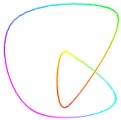
}
}
|
|
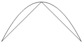
RENDERING RESULT
|
The drawing is composed by two entities:
- A line defined by three vertices.
- A curve defined by the same three vertices of the line.
The curve entity could also be written as “ {{type}{curve}{vertices}{{{0}{0}}{{10}{10}}{{20}{0}}}}”.
Instead of that, giving a name to the line entity allows to inherit its
members and, then, the curve entity whose "inherit" member points to
the entity named "a" can inherit the member "vertices" since it is not
declared in the curve entity but it does in the line entity. In the
other hand, the "type" member is declared in the curve entity so it
cannot be inherited from the line entity. Since the name search
algorithm begins the search in the root entity, the order in which the
entities are defined is meaningless. The algorithm stops the search at
the first match; the comparisons are case sensitive. Inheritance is
recursive, this
means that if the entity A inherits from the entity B and the entity B
inherits from the entity C then the entity A can also inherit from C the
members not directly declared in A or B. If the search algorithm does
not found the entity referenced in the "inherit" member then nothing is
inherited.
The following example illustrates the usage of absolute and relative inheritance:
{
  {type}
  {drawing}
  {folder}
  {
    {
      {type}
      {}
      {line color}
      {{1}{0}{0}}
      {folder}
      {
        {{type}{curve}{inherit}{a}}
        {
          {type}
          {line}
          {vertices}
          {
            {{0}{0}}
            {{10}{10}}
            {{20}{0}}
          }
          {name}
          {a}
          {inherit}
          {.}
        }
      }
    }
    {
      {inherit}
      {a}
      {vertices}
      {
        {{0}{0}}
        {{20}{0}}
      }
      {line color}
      {{0}{0}{1}}
    }
  }
}
|
|
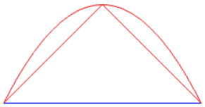
RENDERING RESULT
|
In this case the drawing is composed by:
- A group entity (the "type" member is an empty string, this member
could have been omitted). It declares a "line color" member (red) and a
"folder" member whose child entities are:
- The already known curve entity that inherits from the entity named "a".
- The already known line entity named "a" defined by three vertices.
Now it also declares an "inherit" member whose value is a dot what
means that it inherits from its parent entity, in this case the group
entity.
- An entity that does not declare a type but declares a "vertices"
member, a "line color" member (blue) and inherits from the "a" entity.
The curve entity inherits from the "a" entity the "vertices" member;
additionally it inherits the "line color" member of the group entity
because the line entity named "a" inherits it from its parent which is
the group entity. Therefore the curve entity and the line entity named
"a" are painted in red. The last entity that does not declare an entity
type inherits its "type" member from the entity named "a" so its type
is "line". Since this entity declares its own members "vertices" and
"line color" they are not inherited from the entity named "a", therefore
its color is blue. Group entities are useful for defining common
members to be inherited by its child entities.
While the usage of inheritance is simple, the edition of a drawing that
exploits inheritance may present confusion so it shall be handled with
care. Changes on inherited
entities may lead to unexpected changes in heir entities or may break
inheritance chains resulting in entity disappearing or even
interpretation errors. The Lai4dCL inheritance strategy allows a good
control over what is inherited since the user can select not only which
entity to inherit from using the "inherit" member, but also which
members must not be inherited declaring them in the heir entity, even
with an empty value.
Once the concept of entity has been examined, it is important to
differentiate the concept of node tree from the concept of entity tree.
In any Gosyx structure the elements can be considered nodes of a tree
because an element can have child elements. In a similar way, an entity
can hold child entities within its folder member so this structure can
be considered an entity tree. Any entity itself is a Gosyx structure,
but not all Gosyx structures can be entities, only those structured as a
set of unpacked key-value pairs can be. Therefore an entity tree is
always a Gosyx node tree, but a node tree is not necessarily an entity
tree.
Drawing model
A drawing is a tree structure of
entities in which the root entity is of type "drawing". This means that
the "drawing" entity contains the rest of entities. The most basic
"drawing" entity only needs two members for indicating the type and the
drawing content resulting in the prototype {{type}{drawing}{folder}{}};
the rest of entities are placed within the folder member. If necessary,
the "drawing" entity can also have members for specifying the view
definition or the background color as explained in the section "Standard
entity set".
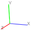
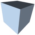
Reference system and drawing units
The geometric information defining the
entities is mainly established through coordinates that, in return, have
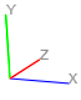
only meaning with respect a reference system. Assuming a normal
disposition in which the
observer sees the positive side of the X axis oriented from left to
right and the positive side of the Y axis oriented from bottom to top,
the standard reference system used in LAI4D has the positive side of the
Z axis oriented towards the observer. It is possible to configure the
opposite orientation for the Z axis including the flag "inverted z" in the member "flags" in
the root "drawing" entity.
There is a reference system for the graphic entities rendered in the
scene. The coordinates of
the geometries defining the entities are expressed in scene coordinates.
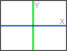
There is another reference system used to position the projected
entities in the viewport named camera reference system. Its origin is at
the center of the viewport, the X axis is parallel to the horizontal
sides of the viewport and the Y axis is parallel to the vertical sides
of the viewport. When the
entities of the scene are projected, their scene coordinates are
processed together with the view configuration in order to obtain the
camera coordinates what, in return, allows to render the scene in the
viewport. The camera reference system can be seen as the reference
system of the screen. The Z coordinate in the camera reference system
indicates the depth and is used to hide far objects behind closer
objects.
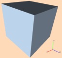
Standard scene
|
|
Inverted Z scene
|
|
Camera reference system
|
|
|
|
|
|
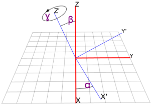
For defining the relative position of the camera reference system with regard the scene reference system three angles are used:
- Longitude: Assuming a zero inclination of the camera, the longitude is
the angle
between the camera's
X' axis and the scene's X axis. A positive angle is in the direction
from X to Y.
- Latitude: Assuming a zero inclination of the camera, the latitude is the
angle
between the camera's
Y' axis and the scene's XY plane. It also is the angle between the
camera's Z' axis
and the scene's Z axis regardless of the inclination of the camera. A
positive angle is
in the direction from the XY plane to the Z axis.
- Inclination: Expresses the rotation around the Z' axis of the camera's
reference
system. When inclination
is zero the camera's X' axis is contained in the XY plane of the scene's
reference
system. Positive inclination is in the same sense as that of a screw
advancing in the
positive direction of the camera's Z' axis (clock wise).
These three angles are the componentes of the member "orientation" in a
"view" entity. A better understanding of the camera orientation can be
achieved
examining the following graphic where the longitude is α, the latitude
is β and the inclination is ɣ. The scene reference system is painted in
red and the camera reference system is painted in blue.
All the coordinates and measures in the scene are unit less.
This means that it is up to the user which physical unit is represented
by the drawing units. The camera coordinates are expressed in pixels.
See also the sections "View control", "view" entity type and "Top-right
corner".
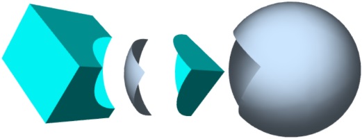
Sub-drawings
Graphic entities like polynets, spheres or any other are not
intended to contain child entities but to define the necessary information
to generate the corresponding rendering. However, in LAI4D, graphic
entities can have a sub-drawing definition in its "folder" member. Thanks to this, the drawing can be
navigated
not only from a spatial point of view, but also from a logical point of
view much the same as a tree of folders in which an entity can be opened
and explored showing its sub-drawing if defined. Here is an example in which a sphere contains a sub-drawing with a box:
{
  {type}
  {sphere}
  {radius}
  {100}
  {folder}
  {
    {
      {type}
      {box}
      {diagonal}
      {{30}{30}{200}}
    }
  }
}
|
The
child entities contained in the "folder" member of a graphic entity are
not rendered until the user expressly navigates into that graphic entity,
moment in which the current drawing shown in the viewport is replaced
by the sub-drawing and that graphic entity becomes the navigated entity. This strategy brings a possibility for defining
complex drawings avoiding the overload of the computing resources
involved in the rendering and the saturation of the viewport with
unnecessary details that cannot be comfortably exploited. In theory,
view entities could also have child entities in the "folder"
member but, since they are not graphic entities, the user wouldn’t be able to
navigate into the corresponding sub-drawing.
In the same way a "drawing" entity is the root of a drawing acting as
parent of the entities contained in its "folder" member, any
graphic entity can be considered the root of the sub-drawing defined by
its "folder" member. The sub-drawings can be nested since any graphic
entity defined in a sub-drawing can declare, in return, a "folder" member with a new
sub-drawing defined in it. The "folder" member does not constitute an
encapsulation so entities defined in a sub-drawing can inherit from
entities defined in the parent drawing and vice versa.
Sub-drawings can be navigated performing a long press event on an entity
and selecting "Navigate into" in the context tools. See
"Context tools" and "Show attachments" for more information.
Interpretation process
Although LAI4D
is capable of rendering several types of entities, the truth is that
there is only one type of intrinsically renderable entity: the polynet.
Any other type of graphic entity is to be converted into a polynet or a
set of polynets during the interpretation process before it can be
rendered. When LAI4D interprets the
entity tree it behaves according to the entity type found following the
next rules:
- Group entity: Its type
is empty or undefined, it is not a graphic
entity and it is not involved in the rendering process. They are used
for grouping purposes building up the tree
structure of the drawing. The child entities found in the "folder"
member will be interpreted. A group entity is also useful for
inheritance since it can have a
name and the child entities can inherit its members. It is to be taken
into account the fact that an entity can inherit the member "type" from
another entity, therefore an entity that does not declare that member
but inherits it may not be considered a group; this is the typical
situation of clone entities which inherit all or most of the members of
the cloned entity including the type. There are other entity types
intended for transformations (transformation, scale, rotation...) that
are not group entities but can work in a similar way.
- View definition: Its
type
is "view", it is not a graphic entity
but it is involved in the rendering process because it defines the
render
frame size and position, the
projection type, the camera orientation, the zoom, etc. A drawing can
have several view definitions each of which defines a render frame and
the way the model is represented in that frame but the current LAI4D
version only
considers the first one which is applied to the main viewport.
- Polynet:
Its type is "polynet" and is a graphic entity. A
polynet defines a set of vertices, a set of faces, a set of lines, a set
of signals and other properties defining colors or line widths for
example.
Signals are 2D graphic entities that are always painted parallel to the
projection plane regardless of the camera orientation. They can be images,
texts, circular dots and polygonals. Each signal is anchored to a vertex
of the polynet so it has a 3D position and is scaled according to depth
in perspective projections. A signal cannot exist outside a polynet.
- Drawing: Its type is "drawing" and it is meant to be the root of the
drawing providing configuration or description members, apart from the
"folder" member that holds the entities to be rendered. Essentially it
is handled as a group entity. It should not be used in any other
situation.
- Other entity types: When LAI4D interprets a drawing it scans the tree structure
searching for intrinsic entities that can be directly understood. If it
founds an entity of not intrinsic type then a cascade conversion process
begins. LAI4D tries to find a conversion function in its registered
libraries suitable for the type of the entity.
If such a function is not found then the entity is ignored, else LAI4D
passes the entity as argument to the function waiting for the conversion
result. The expected result of the function is a new tree structure of
entities that is scanned and interpreted again by LAI4D since it may
not be composed of intrinsic entities. The resulting intrinsic entities
can be polynets or view definitions. This cascade process
continues
until the whole drawing tree is built up only with intrinsic entities.
Such a drawing is called the interpreted drawing.
Each entity type has its own specific members whose information
is processed during interpretation in order to obtain the final polynet that can be rendered.
But an entity can declare other members not related to its type. Those
members are not processed during the conversion of the entity into a polynet, however, they are not
ignored but directly passed to the resulting polynet. This means that an
entity can declare members specifically intended to be used after the
conversion into a polynet. The "Polynet style members" are typically used in this way. Of course an entity can declare members
neither related to its type nor to polynets, and that are completely
ignored by the interpreter remaining on the interpreted drawing but having no effect on the rendering process.
The drawing source is interpreted on start-up and always the design is modified.
Common members in entities
The following members can be used in all or most entity types, here their meaning is explained:
-
type: Indicates the type of
the entity. If the type is unknown to the interpreter then the entity
will be ignored and an issue will be notified. An entity without type is a group entity.
-
inherit: An entity can use a
member "inherit" to hold a string that makes
reference to another entity from which to inherit its
members. If the member "inherit" is undefined or its value is an
empty string
then it means that there is no inheritance. If the value of the member
"inherit" is a dot "."
then it means that the entity must inherit from its parent entity. In
other case it is assumed to be the "name" of another entity. This
strategy allows both an absolute inheritance using a name and a relative
inheritance using a dot as name. See the "Entity model" section
for more details.
-
name: An entity can have an
identifier placed in the member "name" that
should be unique in the entity tree. An empty string is not a valid name
and cannot be referenced. A dot can't be used as name either. The "name"
member is the counter part of the "inherit" member for absolute
inheritance.
-
folder: The folder is the
member that allows to nest entities into another one constructing in
that way the entity tree. It is important to bear in mind that this
containment is a logical containment not a topological one. This means
that the sizes or locations of the entities contained have nothing to do
with the size or location of the container entity. When a graphic
entity
defines a folder member with child entities it is considered to have an
attachment. Entities inside a folder member can be inherited from outside. See the "Sub-drawings" section for more details.
- transform: A list of three 3D vectors
representing the columns of the transformation matrix to be applied to the entity
before rendering; for example
{ {{0.5}{0}{0}} {{0}{0.5}{0}} {{0}{0}{0.5}} }.
This member is applicable to graphic entities. A group entity is not a
graphic entity and this member only has sense in such an entity for
inheritance purposes. For applying a transformation to a group of
entities see the "transformation" entity type. If both "transform" and
"translate" members are
present then the transformation is applied first and the translation
later. Note that a set of entities intended for
transformation is also available.
- translate: A 3D vector
representing the translation vector to be applied to the entity before
rendering; for example
{{0}{10}{20}}. This member is
applicable to graphic entities. A group entity is not a graphic entity and
this member only has sense in such an entity for inheritance purposes.
For applying a translation to a group of entities see the
"transformation" entity type.
If both "transform" and "translate" members are present then the
transformation is applied first and the translation later. -
user data: It is intended to
hold any data the user needs. This data can be simple such as a string or a
number; or it can be a more complex data structure. When an entity
defines an user data member it is considered to have an attachment. See the "Context tools" section for more details.
- link: It defines an
URL
which can be opened in a new browser window as a standard HTML link. The
link can point to any common HTML resource such as images, HTML pages,
or even other LAI4D drawings.
The URL can also be a data URI obtained with the utility "Base64 file
encoder". When an entity defines a link
member it is considered to have an attachment. See the "Context tools"
section for more details.
- ignore:
When its value is
non-zero indicates that the interpreter must ignore the entity. It is
intended to permit the hiding of entities in the drawing. A hidden
entity can be inherited and, if the heir entity declares the member
"ignore" then the heir entity can be visible while the inherited entity
is invisible. If a group entity (no type) is ignored then the
entities contained will also be ignored regardless of whether they define the "ignore" member
or not, but they still can be inherited; this is particularly useful
for defining invisible libraries of components that can be replicated in
several parts of the drawing through inheritance. See the "Selection
&
visibility" section for more details.
- labels: It is intended to
contain simple text pieces that label the entity. As opposed to the
"folder" member that allows a hierarchical organization of the entities,
the "labels" member allows to group entities in at will.
Polynet style members
Graphic entities can declare other members not
directly related to their type, particularly some involved in polynet
styling
like "line color" or "face color" for instance. Since any graphic entity
is converted into a polynet during interpretation, those members
unrelated to the entity type but related to polynets are directly passed
to the resulting polynet.
The meaning of such style members is explained next:
- line width: The line width in pixels. By default 1.
- line color: A set of up to 4 numbers in the range [0, 1] with
the components of a RGBA color to be applied to line elements. By default {{0}{0}{0}{1}}.
- face color: A set of up to 4 numbers in the range [0, 1] with
the components of a RGBA color to be applied to face elements. By default {{0.8}{0.9}{1}{1}}.
- face curved: If this member is non-zero then the brightness of
the faces of the polyhedron is rendered in a manner that visually
produces a curved surface effect. This option is only considered in
WebGL context.
- fill: If this member is non-zero and there is not a "faces" member then
for each line definition in the member "lines" the corresponding filled
polygon will be rendered. This member is intended to allow the
generation of surface geometries from linear entities.
- stroke: If this member is non-zero and there is not a "lines"
member then for each face definition in the member "faces" the
corresponding closed stroked polygon will be rendered. This member is
intended to allow the generation of linear geometries from surface
entities.
- vertex colors:
A list of RGBA colors, one for each vertex. When
rendering the faces or lines of the polynet, the rendering engine
interpolates linearly the colors between the vertices in WebGL
rendering context, or calculates the averaged color of the vertices in
canvas 2D rendering context. The colors
exceeding the number of vertices are ignored and missing colors are
replaced by transparent black. This member overrides the
members "line color" and "face color" if defined.
When the style members are not declared the renderer internally applies
the default values. Each entity type can have its own specific style
members.
Standard entity set
This is the set of entities intended for general use.
polynet
It builds a polynet entity which can contain faces, lines and signals. A
polynet defines a set of vertices, a set of faces, a set of lines, a set
of signals and styles for them.
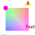
Signals are 2D graphic entities that are always painted parallel to the
projection plane regardless of the camera orientation. They can be images,
texts, circular dots and polygons. Each signal is anchored to a vertex
of the polynet so it has a 3D position. Details:
The polynet is the only intrinsically
renderable entity. Any other type of graphic entity is to be converted
into a polynet or a set of polynets before it can be rendered. Each face
or line is defined as a set of indices that points to the given
vertices. These are the members of this entity type:
- vertices: Mandatory. A list of 3D points each of which is a list of three
coordinates XYZ, as for instance {{0.5}{30}{7.34}}. Actually each point
could have less than three coordinates; the last omitted coordinates
will be replaced by 0.
- faces: A list of faces each of which is a set of indices that points to the given vertices,
as for instance {{0}{1}{2}{3}}. A face can have any number of vertices
greater than two and, in theory, they should be in the same plane but
this requirement is not mandatory. LAI4D does not perform any checking
in the given set of vertices, it simply projects the vertices and paints
the corresponding polygon which may seem strange if that set of
vertices is not well constructed. LAI4D triangulates the faces always in
WebGL and, if configured, in canvas 2D too.
- lines: A list of lines each of which is a set of indices that
points to the given vertices, as for instance {{0}{1}{2}{3}}. A line can
have any number of vertices greater than one. In order to build a closed line the last index must coincide with the first one.
- signals: A container of signal entities. The signals can be of type
"signal image", "signal text", "signal dot", "signal poly". The order in which
the signals are declared in this member is important because when a
group of signals share the same anchored vertex they have the same depth
and there is no other way to know the painting order. See the
corresponding signal definition for more details.
Additionally this entity can declare the "Polynet style members" which can also be used in other entities.
DESCRIPTOR
|
PROTOTYPES
|
USAGE SAMPLE
|
RESULT
|
descriptor
|
prototypes
|
|
|
signal image
Generates an image with the given source,
offset and size. A signal entity can only be part of the "signals"
member of a polynet. Details:
These are the members of this entity type:
- anchor: Mandatory. Index of the vertex to which this signal is anchored.
- offset: A set of two numbers with the X and Y offsets of the bottom-left corner of the signal with respect the anchor point.
- size: Mandatory. A set of two numbers with the width and height of the signal.
- src:
Mandatory. A string with the path of the image
file as it should be assigned to the "src" attribute of an IMG element.
This string can also be a data URI obtained with the utility "Base64
file encoder".
Images are loaded asynchronously so their visualization may not be
immediate. If the image file cannot be loaded no error is raised.
The dynamic loading of files can be problematic for a number of
reasons. The simplest cause could be an error in the file path. But it
can also be a cross domain restriction or a limitation of the browser
when working offline.
|
DESCRIPTOR
|
PROTOTYPES
|
USAGE SAMPLE
|
RESULT
|
proto |
proto
|
|
|
signal text
Generates a text with the given string,
styles, offset and size. A signal entity can only be part of the
"signals" member of a polynet. Details:
These are the members of this entity type and their meanings:
- anchor: Mandatory. Index of the vertex to which this signal is anchored.
- offset: A set of two numbers with the X and Y offsets of the bottom-left corner of the signal with respect the anchor point.
- text: Mandatory. A string with the text to be rendered.
- line color: The RGBA color used for rendering the signal.
- font size:
Mandatory.
A number with the height of the text.
- font style: Any valid value for the font-style CSS property such as "italic" for instance; "normal" by default.
- font weight: Any valid value for the font-weight CSS property such as "bold" for instance; "normal" by default.
- font family: Any valid value for the font-family CSS property such as "Arial" for instance; "monospace" by default.
In
WebGL rendering context text signals are created in a canvas 2D context
and then passed to the WebGL context as a texture image. This could
result in a partial loss of quality.
DESCRIPTOR
|
PROTOTYPES
|
USAGE SAMPLE
|
RESULT
|
proto |
proto
|
|
|
signal dot
Generates a circular dot with the given radius
and color. A signal entity can only be part of the "signals" member of a
polynet. Details:
These are the members of this entity type and their meanings:
- anchor: Mandatory. Index of the vertex to which this signal is anchored.
- radius: Radius of the circle that
represents the dot.
- line color: The RGBA color used for rendering the signal.
DESCRIPTOR
|
PROTOTYPES
|
USAGE SAMPLE
|
RESULT
|
proto |
proto
|
|
|
signal poly
Generates a polygonal line with the given
geometry and styles. A signal entity can only be part of the "signals"
member of a polynet. Details:
These are the members of this entity type and their meanings:
- anchor: Mandatory. Index of the vertex to which this signal is anchored.
- points: Mandatory. A list of 2D points each of which is a list of two
coordinates XY, as for instance {{0.5}{30}}. Actually each point
could have less than two coordinates; the last omitted coordinates
will be replaced by 0.
- line width: The line width. By default 1.
- line color: The RGBA color used for rendering the signal.
DESCRIPTOR
|
PROTOTYPES
|
USAGE SAMPLE
|
RESULT
|
proto |
proto
|
|
|
face
It builds a simple polygonal face. The only
necessary data are the vertices of the polygon. A face can have any
number of vertices greater than two and, in theory, they should be at the same plane but
this requirement is not mandatory. Details:
LAI4D does not perform any checking in the
given set of vertices, it
simply projects the vertices and paints the corresponding polygon which
may seem strange if that set of vertices is not well constructed.
LAI4D triangulates the faces always in WebGL and, if configured, in
canvas 2D too. Line styles are ignored unless the widget is configured
to stroke the faces. See the "Options" section for more details.
DESCRIPTOR
|
PROTOTYPES
|
USAGE SAMPLE
|
RESULT
|
proto |
proto
|
|
|
line
It builds a simple polygonal line. The only
necessary data are the vertices of the polygon. Additionally it can be
indicated if the polygonal line is closed providing the member "closed"
with a non-zero value; by default the line is not closed. Details: Face styles are ignored.
DESCRIPTOR
|
PROTOTYPES
|
USAGE SAMPLE
|
RESULT
|
proto |
proto
|
|
|
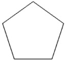
polygon
It builds a regular 2D polygon with the given number of sides and circumscribed to a circle of the given
radius. Details:
The entity is generated at the plane Z = 0
with the center at the origin. For changing the center the member
"translate" can be used. The algorithm places the side with the lowest Y
parallel to the X axis. These are the members of this entity type and
their meanings:
- radius: Mandatory. Positive radius if the circle to which the polygon is circumscribed to.
- sides: Mandatory. An integer greater than 2 indicating the number of sides of the polygon.
DESCRIPTOR
|
PROTOTYPES
|
USAGE SAMPLE
|
RESULT
|
proto |
proto
|
|
|
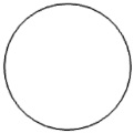
circle
It builds a 2D circle with the given
radius. By default the circle is complete but the user can indicate an
angle in the member "angle" in order to obtain a partial arc. Details:
The entity is generated at the plane Z = 0
with the center at the origin. To get an ellipse, or to place the circle
at another position of the 3D space the members "transform" and
"translate" can be used. The density of the polygon that represents the
circle depends on the configuration parameter "Tessellation". See the
"Options" section for more details. These are the members of this entity
type and their meanings:
- radius: Mandatory. Positive radius if the circle.
- angle: Optional. The angle is expressed in degrees. If the member
"angle" is provided then an arc with the given amplitude is generated in
the standard way, it is to say, from the X axis growing anticlockwise.
DESCRIPTOR
|
PROTOTYPES
|
USAGE SAMPLE
|
RESULT
|
proto |
proto
|
|
|
curve
It builds a 3D curved line interpolated from the
given set of points in the "vertices" member. Declaring the member
"closed" with a non-zero value will build a closed curve.
Details: The curve
generated is
invariant before linear affine transformations that preserve the form of
the geometry such as rotations or uniform scalings. The curve generated
from a subset of
vertices is equal to the curve fragment corresponding to that subset of
vertices but the first and last segments. If two consecutive vertices
are equal then the corresponding segment evaluates to a single point. If
two consecutive vertices are equal and the next two consecutive
vertices are also equal then a straight segment is generated between the
two pairs of vertices. Thanks to this the "curve" entity can represent
linear geometries mixing straight and curved segments. That is the
reason because this interpolation algorithm is used by other entity
types as a generic profile generator. The colors of the "vertex colors"
member are also
interpolated what can be used for artistic purposes. The density of the
polygon that represents the curve depends on the configuration
parameter "Tessellation".
DESCRIPTOR
|
PROTOTYPES
|
USAGE SAMPLE
|
RESULT
|
proto |
proto
|
|
|
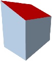
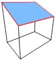
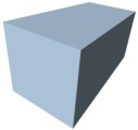
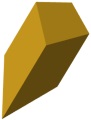
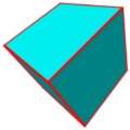
box
It builds a box from the given diagonal with the edges parallel to the reference system axes.
Details: The
member "diagonal" contains the three dimensions of the box. One of
the vertices is at the origin and the opposite one is at the coordinates
indicated by the member "diagonal".
DESCRIPTOR
|
PROTOTYPES
|
USAGE SAMPLE
|
RESULT
|
proto |
proto
|
|
|
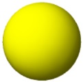
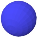
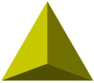
sphere
It builds a compact sphere with the given
radius. Details:
The entity is a polyhedron generated with a
recursive algorithm that begins with a regular octahedron. An iteration
of the algorithm divides each triangular face of the previous iteration
into four new triangular faces. The entity is created with the center at
the origin. For changing the center the member "translate" can be used.
The member "face curved" should be provided with a non-zero value in
order to obtain a curved face brightness effect instead of a polyhedron
brightness effect. These are the members of this entity type and their
meanings:
- radius: Mandatory. Positive radius if the sphere.
- iterations: Optional. If the member "iterations" is provided then
its value will be used for the number of iterations; else the number of
iterations will be estimated according to the configuration parameter
"Tessellation". If "iterations" is 0 then a regular octahedron is
obtained; with 4 iterations a sphere of great quality is obtained.
DESCRIPTOR
|
PROTOTYPES
|
USAGE SAMPLE
|
RESULT
|
proto |
proto
|
|
|
globe
It builds a standard polar globe with the given
radius and the specified number of parallels and meridians. Details:
The meridians are lines from one pole of the
globe to the other one. The parallels are closed lines (last vertex
equal to the first), two of them correspond to the poles and have all
the vertices located at the pole. The resulting entity has (parallels *
meridians) vertices. The poles are at the Z axis. The entity is created
with the center at the origin. For changing the center the member
"translate" can be used. The member "face curved" should be provided
with a non-zero value in order to obtain a curved face brightness effect
instead of a polyhedron brightness effect. These are the members of
this entity type and their meanings:
- radius: Mandatory. Positive radius if the globe.
- meridians: Mandatory. The desired number of meridians must be at least 3.
- parallels: Mandatory. The desired number of parallels must be at least 3.
DESCRIPTOR
|
PROTOTYPES
|
USAGE SAMPLE
|
RESULT
|
proto |
proto
|
|
|
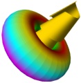
revolved
It builds a surface of revolution with the
given profile around the Z axis that can optionally be a screw like surface. By default the amplitude of the
revolution is complete, but an optional member "angle" can be provided
for indicating another amplitude. Cones and cylinders can be generated using a straight segment as profile. Details:
The density of the polyhedron that represents
the generated surface depends on the configuration parameter
"Tessellation". The member "face curved" should be provided with a
non-zero value in order to obtain a curved face brightness effect
instead of a polyhedron brightness effect. Obtaining a "revolved" entity
can be easily achieved creating a "curve" entity and replacing the
value of its member "type" by "revolved". These are the members of this
entity type and their meanings:
- vertices: Mandatory. The profile is defined in the "vertices"
member by a set of 3D points which will be interpolated to generate a
curve with the same algorithm as the "curve" entity so it does not need
to be planar. Since the rotation axis is the Z axis the profile should
not be defined in a plane parallel to the XY plane, although it is not
an error. The profile needs at least two points.
- closed: Optional. By declaring the member "closed" with a non-zero value the profile will be a closed curve.
- vertex colors: Optional. A list of RGBA colors; one color per vertex of the profile.
- angle: Optional. The angle is expressed in degrees. The sense of
rotation for a positive angle is the same as that of a screw advancing
in the direction of the axis.
- advance: Optional. Screw like surfaces can be generated
using the optional member "advance" which indicates the total advance
length of the screw.
DESCRIPTOR
|
PROTOTYPES
|
USAGE SAMPLE
|
RESULT
|
proto |
proto
|
|
|
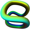
pipe
It builds a pipe surface with the
given profile along the given guideline. Both profile and guideline can
be closed. Extruded surfaces can be generated using a straight segment
as guideline. Details:
The profile is assumed to be referenced to
the origin {0,0,0} and to the orientation defined by the Z axis. To take
this into account is important because the guideline can be defined
anywhere in the space regardless of how the profile is defined (this is also useful for inheritance purposes). The
surface is built translating copies of the profile from the origin
(reference point of the profile) to the points of the guideline and, at
the same time, reorienting the profile copy making the reference Z axis
tangent to the guideline. Due to the generator algorithm tries to
achieve geometric coherence for closed guidelines, the surface may look a
bit twisted along curved fragments of the guideline. These are the
members of this entity type:
- vertices: Mandatory. A set of 3D points defining the profile. It
will be interpolated to generate a curve with the same algorithm as the
"curve" entity so it does not need to be planar. The profile needs at
least two points.
- closed: Optional. If non-zero then indicates that the profile will be a closed curve.
- vertex colors: Optional. A list of RGBA colors; one color per vertex of the profile.
- guide. Mandatory. A set of 3D points defining the guideline. It will
be interpolated to generate a curve with the same algorithm as the
"curve" entity so it does not need to be planar. The guideline needs at
least two points
- closed guide: Optional. If non-zero then indicates that the guideline will be a closed curve.
The colors of the "vertex colors" member are also interpolated what can be used for artistic purposes.
The density of the polyhedron that represents the generated surface
depends on the configuration parameter "Tessellation". The member "face
curved" should be provided with a non-zero value in order to obtain a
curved face brightness effect instead of a polyhedron brightness effect.
DESCRIPTOR
|
PROTOTYPES
|
USAGE SAMPLE
|
RESULT
|
proto |
proto
|
|
|
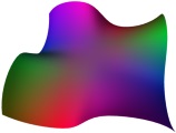
mesh
It builds a simple tabulated surface based on
an array of vertices given in the member "table". The member "smooth"
allows to generate a curved surface that passes through the given set of
vertices. This entity is
typically used for building irregular surfaces from arrays of points or
organic surfaces based on frames, and can also be used for ruled surfaces. Details:
The vertices are distributed as a set of rows
in a table. The number of vertices in a row is the number of columns of
the table and must be the same for all rows. Each face is defined by
four vertices.
These are the members of this entity type:
- table: Mandatory. The list with the rows of vertices. It needs
at least two rows, and a row needs at least two vertices in which case
the mesh would have only one face.
- closed s: Optional. If non-zero then indicates that the surface must
be closed in the "s" direction which corresponds to the rows.
- closed t: Optional. If non-zero then indicates that the surface must be
closed in the "t" direction which corresponds to the columns.
- smooth: Optional. If non-zero then indicates that the surface must be smooth. This member allows to
create organic surfaces with an accurate control over the points through
which the surface must pass. The density of the polyhedron that
represents the surface depends on the configuration parameter
"Tessellation". The smoothed surface is generated using an interpolation
algorithm based on the one used for the "curve" entity. This fact
confers to the generated surface the following properties:
- The surface is invariant before linear affine transformations that
preserve the form of the geometry such as rotations or uniform
scalings.
- The resulting geometry is the same if the given vertices are arranged in columns instead of rows.
- The surface generated from a subset of vertices is equal to the
surface fragment corresponding to that subset of vertices but the
bounding area.
- If several contiguous vertices coincide then the surface evaluates
in a peak or an edge for those points. This property allows to generate
surfaces combining curved and flat areas as well as edges.
- table colors: Optional. A collection with lists of RGBA colors; one
list per row of vertices. Each list should have one color for each
vertex of the
corresponding table row. Missing colors will be replaced by transparent.
The colors will be interpolated if the member "smooth" is non-zero.
The member "face curved" should be provided with a non-zero value in
order to obtain a curved face brightness effect instead of a polyhedron
brightness effect.
DESCRIPTOR
|
PROTOTYPES
|
USAGE SAMPLE
|
RESULT
|
proto |
proto
|
|

|
patch
It builds a surface interpolated from the
given four sides that bounds the surface. This entity is typically used
for organic modelling and can also be easily configured for obtaining ruled surfaces. Details:
When defining the sides the idea of a closed
ring must be kept in mind so each side must be connected to the next one
and to the previous one, no matter the order with which the points are
defined in the sides. As a ring of four sides, the side 0 is the
opposite of the side 2 and the side 1 is the opposite of the side 3.
These are the members of this entity type:
- ring: Mandatory. The list with the 4 sides. Each side is defined
by a set of points which will be interpolated to generate a curve with
the same algorithm as the "curve" entity. At least two points are to be
provided per side but the sides can have different number of points. The
length of any side can be 0.
- s: Optional. Indicates the number of divisions that must be
generated in the sides 0 and 2; if the value is less than 1 or undefined
then it will be estimated from the configuration parameter
"Tessellation".
- t: Optional. Indicates the number of divisions that must be
generated in the sides 1 and 3; if the value is less than 1 or undefined
then it will be estimated from the configuration parameter
"Tessellation".
- ring colors: Optional. A collection with 4 lists of RGBA colors; one
list per side. Each list should have one color for each vertex of the
corresponding side. Missing colors will be replaced by transparent. When
the surface is generated the resulting colors are interpolated from the
values of this member.
The member "face curved" should be provided with a non-zero value in
order to obtain a curved face brightness effect instead of a polyhedron
brightness effect.
DESCRIPTOR
|
PROTOTYPES
|
USAGE SAMPLE
|
RESULT
|
proto |
proto
|
|
|
transformation
Applies a general affine transformation to the
target
entities defined in the "apply" member according to the four pairs of
points provided in the member "pairs". The generic affine transformation
involves a translation and a change from one basis to other one. With
the optional member "align" the operation can be processed as an
alignment. Details:
Each basis is defined by four points: one
origin and the three edges of the three vectors representing the axes.
Each pair of points entered defines the correspondence between the
points in both bases. For example, the first pair of points defines the
correspondence between the origins, the second pair of points defines
the correspondence between the edges of the first axis, and so on. See the command Transform entities for more information.
Depending on the number of pairs of points provided the operation can
be:
- simple translation
- translation + rotation + elongation along a line
- translation + plane alignment + planar deformation
- translation + complete transformation
If the bases present linear combination the operation may be unfeasible.
As any other entity, this one can declare the members "transform" and
"translate" in which case the result is the combination of both
transformations. These are the members of this entity type and their
meanings:
- apply: Mandatory. Container of the entities to which the operation is applied.
- pairs:
Optional. This member is a collection of pairs of points defining the
correspondences between the two bases. If provided then the first pair
of points is mandatory and each pair must have at least two points, the
rest is ignored. If not provided then no transformation is applied.
- align: Optional. If non-zero then indicates that the transformation
is a 3D alignment. The alignment involves a translation and a rotation.
The fourth pair of points will be ignored. See the command Align
entities for more information.
DESCRIPTOR
|
PROTOTYPES
|
USAGE SAMPLE
|
RESULT
|
proto |
proto
|
|
|
rotation
Applies a rotation to the target
entities defined in the "apply" member. The user shall indicate an axis and an angle. Details:
These are the members of this entity type and their meanings:
- apply: Mandatory. Container of the entities to which the operation is applied.
- axis: Mandatory. The axis must have two points. If the second point
of the axis is not provided then it is assumed that the rotation axis is
parallel to the Z axis {{0}{0}{1}}, as if it were a 2D rotation in the
XY plane. The length of the axis is meaningless.
- angle:
Optional. If the angle is not provided then 0 is assumed. The angle is
expressed in degrees. The sense of rotation for a positive angle is the
same as that of a screw advancing in the direction of the axis.
DESCRIPTOR
|
PROTOTYPES
|
USAGE SAMPLE
|
RESULT
|
proto |
proto
|
|
|
scale
Applies a scale to the
entities in the "apply" member. The user should indicate a scale factor and, optionally, an origin for that scaling.
Details:
These are the members of this entity type and their meanings:
- apply: Mandatory. Container of the entities to which the operation is applied.
- origin: Optional. If the member "origin" is not provided then it is
assumed {{0}{0}{0}}. The center of scaling is the given origin.
- factor: Optional. If the member "factor" is not provided then 1 is assumed.
DESCRIPTOR
|
PROTOTYPES
|
USAGE SAMPLE
|
RESULT
|
proto |
proto
|
|
|
symmetry
Calculates the symmetric to the
entities in the "apply" member. The symmetry can be defined with respect a
point, with respect a straight line or with respect a plane. Details:
These are the members of this entity type and their meanings:
- apply: Mandatory. Container of the entities to which the operation is applied.
- references: Mandatory. The member "references" can hold from one up to three 3D points. If one
point is given then the symmetry is with respect that point. If two
points are given then the symmetry is with respect a straight line. If
three points are given then the symmetry is with respect a plane.
DESCRIPTOR
|
PROTOTYPES
|
USAGE SAMPLE
|
RESULT
|
proto |
proto
|
|

|
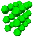
cartesian
Generates a 3D cartesian array layout copying the target
entities defined in the "apply" member according to the given array dimensions and cell size. Details:
These are the members of this entity type and their meanings:
- apply: Mandatory. Container of the entities to which the operation is applied.
- dimensions: Mandatory. The member "dimensions" is composed of three integers that represent the
number of cells in the X, Y and Z directions; the integers must be
greater than 0.
- cell: Mandatory. The member "cell" is composed
of three numbers representing the signed distances between the copies in
the X, Y and Z directions.
DESCRIPTOR
|
PROTOTYPES
|
USAGE SAMPLE
|
RESULT
|
proto |
proto
|
|
|
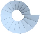
polar
Generates a 3D polar array layout copying the target
entities defined in the "apply" member according to the given angle and height increments.
Details:
The polar distribution is built around the Z axis.
These are the members of this entity type:
- apply: Mandatory. Container of the entities to which the operation is applied.
- steps: Mandatory. An integer value indicating the number of
elements of the array, including the original one. It must be greater
than 0.
- angle step: Angle increment expressed in degrees corresponding to each step. If omitted then 0 is assumed.
- height step: Height increment in the Z axis corresponding to each step. If omitted then 0 is
assumed. This member combined with the "angle step" member allows to
generate solenoidal distributions.
- base: A 3D point considered as base point for the set of
entities to be copied. If provided then the elements are translated to
the destination points of the array. If omitted then the elements will
be rotated as they are copied according to the "angle step" member.
DESCRIPTOR
|
PROTOTYPES
|
USAGE SAMPLE
|
RESULT
|
proto |
proto
|
|
|
view
It is not a graphic entity
but it is involved in the rendering process. A view entity defines the
render
frame size and position, the
projection type, the camera orientation, the zoom, etc.
Details:
A drawing can have several view definitions
each of which defines a render frame and how the model is represented in
that frame but the current LAI4D version only considers the first one
which is applied to the main viewport. It is recommended to place the
default view entity in the member "view" of the root drawing entity.
These are the members of this entity type:
- projection: A keyword identifying the type of projection:
- parallel: For parallel projections.
- perspective: For perspective projections.
- orientation: 3 numbers
corresponding to longitude, latitude and inclination of the camera. All expressed in degrees.
- point: 3D coordinates corresponding
to the origin of the camera's reference
system (point of view) expressed in scene coordinates.
- zoom: A number with:
- A length for parallel projections (scene's length
represented in the shortest side
of the viewport).
- A field of view angle for perspective projections
(camera's field of view represented
in the shortest side of the viewport) expressed in degrees.
- target: The Z coordinate in camera coordinates corresponding to the point
around which the camera rotates in the orbital navigation mode (camera target). The
render does not depends on it and it is only used in the event
management for controlling the view configuration.
- far light direction: 3D vector with the direction
of the far directional light. It is assumed to be fixed to the camera
and must be expressed in camera coordinates. The sense and length of the
vector are meaningless.
- far light factor: A number with the far directional light proportion,
between [0,1]. It represents the proportion of diffuse reflected light, the rest is assumed to be ambient light.
- focus reflection factor: A number indicating the intensity of reflected directional light that is focused,
between [0,1]. This white light is added to the standard brightness leveraging its effect.
The
function "Set current view" will set the current view definition in the
member "view" of the root "drawing" entity. See also "Reference system
and drawing units".
DESCRIPTOR
|
PROTOTYPES
|
USAGE SAMPLE
|
RESULT
|
proto |
proto
|
|
|
drawing
It encapsulates a drawing containing the
graphic entities, view definitions and some metadata. Some of its
members directly affect how the drawing is initially shown. Details:
These are the members of this entity type:
- folder: The "folder" member can contain any type of entity, even
view definitions. Entities with empty or undefined type will be handled
as groups. Entities with unknown type will be ignored.
- view: The value of the "view" member is intended to be the default view
definition and, if provided, that view definition will have priority
over those contained in the "folder" member. This is the initial view configuration used when the drawing is loaded.
- background color: The RGBA color used as background for the drawing.
- flags: This member is intended to contain a set of keywords whose
mere presence indicates a configuration to be used when the drawing is
loaded. Most of the keywords are directly related to
one of the configurable options available through the "Tools menu". If
the concurrency of several flags generates a conflict then the following
flag order is used as a priority selector.
These are the currently supported keywords and their meaning:
- no camera inclination: It is equivalent to having checked the option "No camera inclination".
- show reference system: It is equivalent to having checked the option "Show reference system".
- no lighting : It is equivalent to having unchecked the option "Apply lighting".
- inverted z: The default reference system used in LAI4D is the
standard one in many regions but in other regions the commonly used
reference system has the Z axis with the opposite sense to that found in
LAI4D. If the default sense of the Z axis is not comfortable for the
user then he can include the flag "inverted z" what
indicates that the Z coordinates of camera and scene are to be inverted
for rendering. This flag should be changed only in a new drawing. See
"Reference system and drawing units" for more details. The "inverted z" flag is an experimental feature.
- camera orbital: Sets the camera mode to orbital navigation.
- camera polar: Sets the camera mode to polar navigation.
- camera pan: Sets the camera mode to pan navigation.
- version: Two integers with the functional and build version of LAI4D.
- title: A string with the drawing title.
- description: A string with the drawing description.
- author: A string with the name of the author.
The functions under the "Drawing metadata" menu group will set the
metadata members of the root "drawing" entity to their current values.
DESCRIPTOR
|
PROTOTYPES
|
USAGE SAMPLE
|
RESULT
|
proto |
proto
|
|
|
Extended entity set
This is the set of entities intended for special purposes.
program
Generates entities evaluating the algorithm described in the "code" member. The source code of the JS program
contained in the member "code" is evaluated expecting an array or simple value as
result, that is then converted into a Gosyx structure which will be finally
interpreted as a normal entity. The optional member "variable" can be used for passing arguments to the JS program. Details:
Sometimes the standard entities offered by a
CAD application are not enough for the intended design. LAI4D breaks
this limitation facilitating the algorithmic generation of entities
without restrictions. The "program" entity is the simplest way
for a developer to generate entities from a programing language. Taking
into account that an entity is a Gosyx structure, and considering that a
Gosyx structure can be assimilated to a JS string or number in case of
being simple, or to a JS array in case of being compound (which is the
normal situation); the strategy consists of generating that array or
simple value as the program's result in order to be later converted by
the interpreter into
a Gosyx structure that
will be finally handled as an entity in the usual way. For example, the
Gosyx structure shown at the left can be expressed as the JS array shown
at the right and vice versa:
{
  {type}
  {face}
  {vertices}
  {
    {{0}{0}{0}}
    {{0}{2}{0}}
    {{0}{2}{2}}
  }
}
|
|
[
  "type",
  "face",
  "vertices",
  [
    [0, 0, 0],
    [0, 2, 0],
    [0, 2, 2]
  ]
]
|
|
Compound nodes are assimilated to JS arrays and simple nodes are
assimilated to their JS counterparts (strings or numbers). This strategy
permits the programmer to implement the solution without any knowledge
or constrain derived from the LAI4D or Gosyx APIs. The accepted simple
JS values are
converted into simple Gosyx nodes according to the following rules:
- Numbers and Strings directly become the simple values.
- Booleans: true is converted into 1, false into 0.
- null or undefined are converted into an empty string.
The program entity currently supports only JavaScript. The content of the "code" member will be evaluated in a sentence like:
result = (function(){return eval(code);})();
Then it will try to convert the result into a Gosyx structure. This
Gosyx structure can be a graphic entity such as a polynet, or it can be a
group entity (an entity without "type" member) containing more entities
in its "folder" member, or it can even be another program entity. It is
to say, the result can be any entity known by the interpreter. Any
problem will be notified as an issue in the usual way so it can be useful to include throw sentences in order to handle custom errors.
The content of the "code" member can be as simple as the source of a JS array:
{{type}{program}{code}{["type","sphere","radius",20]}}Or
it can be a complete algorithm such as:
{{type}{program}{code}{(function ()|123|
    /*Represent function Y = sinus(X)*/
    var result = ["type","curve","vertices",[]];
    for(var x = 0; x <= 360; x+=10)|123|
        result[3].push([x*Math.PI/180, Math.sin(x*Math.PI/180)]);
    |125|
    return result;
|125|)();}}
|
The user will normally use his preferred JS editor to create the
JS code that will become the content of the "code" member. It is
important to mention that the JS code will normally use
characters which are considered special in Gosyx syntax (curly brackets
for instance); therefore, when composing the "program" entity, it is
recommended the usage of a tool such as
the "Tree explorer", that includes the necessary syntax conversion
capabilities, in order to generate it without
incidences.
While a "program" entity can make use of the members "name" or
"inherit", as any other entity can, it is to be noted that entities
resulting from the interpretation of a "program" entity
cannot inherit and cannot be inherited because they are not part of the
original entity tree. The user shall avoid the algorithmic generation of
entities with the members "name" or "inherit".
This is enough for implementing the algorithmic generation of entities
and, as it can be seen, there is no need of using any kind of API for
this purpose. Despite that, LAI4D provides a JS object named
" AppLai4d" which is reachable within the JS code and is intended to
offer the programmer additional functionality.
 The AppLai4d object has the following custom properties: The AppLai4d object has the following custom properties:
|
Returns the JS-converted value of the "variable" member of the "program" entity.
AppLai4d.variable
The "program" entity can have a "variable" member that
works in
the opposite sense to that of the "code" member, it is to say, its value
(a Gosyx structure) is
converted into a JS object which is made available to the JS code under
the name "AppLai4d.variable". This member will typically contain a
number or a set of numbers which will be converted into a JS number or a
JS array respectively, but it can hold any structure or simple value. It
is intended to allow the passage of arguments to the program code in a
clean way
without the need of modifying the code itself. If the member "variable"
is not declared then undefined is passed to the JS object
"AppLai4d.variable"; if
it is simple then it is converted into a number (if possible) or a
string; if it is compound then it is converted into an array (note that an
empty Gosyx node is a simple value so it will be converted into an empty
string, not an empty array). From an
interpretation point of view this member is optional but the JS program
written in the "code" member may require it with a specific structure;
therefore an improper use of the "variable" member may result in an
error raised during the evaluation of the "code" member. An elemental
example of the usage of the member "variable" could be:
{{type}{program}{code}{["type","sphere","radius",AppLai4d.variable]}{variable}{20}}.
Returns the value of the configurable parameter "Tessellation".
AppLai4d.tessellation
The configurable parameter "Tessellation" indicates the
number of segments of the polygon that represents a circle. This value
could be used when working with curved geometries. See the
"Tessellation" section for more details.
Returns the length of the vector argument.
result = AppLai4d.VecLen(vec)
PARAMETER
|
DESCRIPTION
|
result
|
A number.
|
vec
|
A vector (array of numbers) of any number of
elements. |
Returns the vector resulting from multiplying
the vector argument by
the scalar
argument.
result = AppLai4d.VecNum(vec, num, result)
PARAMETER
|
DESCRIPTION
|
result
|
A vector (array of numbers) with the
result.
|
vec
|
A vector (array of numbers) of any number of
elements. |
num
|
A number.
|
result
|
Optional. An already existing array can also be passed as optional result argument in order to avoid generating a new
array for the result. The vec argument can be used as the optional result argument without conflicts. |
Returns the vector normalized (length = 1).
result = AppLai4d.VecNorm(vec, result)
PARAMETER
|
DESCRIPTION
|
result
|
A vector (array of numbers) with the
result.
|
vec
|
A vector (array of numbers) of any number of
elements. |
result
|
Optional. An already existing array can also be passed as optional result argument in order to avoid generating a new
array for the result. The vec argument can be used as the optional result argument without conflicts. |
Returns the vector resulting from adding the
arguments.
result = AppLai4d.VecAdd(ve1, ve2, result)
PARAMETER
|
DESCRIPTION
|
result
|
A vector (array of numbers) with the
result.
|
ve1
|
A vector (array of numbers) of any number of
elements. |
ve2
|
A vector (array of numbers) of any number of
elements. |
result
|
Optional. An already existing array can also be passed as optional result argument in order to avoid generating a new
array for the result. Either ve1 or ve2 argument can be used as the optional result argument without conflicts. |
Returns the vector resulting from subtracting
the second argument to
first one.
result = AppLai4d.VecSub(ve1, ve2, result)
PARAMETER
|
DESCRIPTION
|
result
|
A vector (array of numbers) with the
result.
|
ve1
|
A vector (array of numbers) of any number of
elements. |
ve2
|
A vector (array of numbers) of any number of
elements. |
result
|
Optional. An already existing array can also be passed as optional result argument in order to avoid generating a new
array for the result. Either ve1 or ve2 argument can be used as the optional result argument without conflicts. |
Returns the dot product of two vectors.
result = AppLai4d.VecDot(ve1, ve2)
PARAMETER
|
DESCRIPTION
|
result
|
A number.
|
ve1
|
A vector (array of numbers) of any number of
elements. |
ve2
|
A vector (array of numbers) of any number of
elements. |
Returns the cross product of two 3D vectors.
result = AppLai4d.VecCross3D(ve1, ve2, result)
PARAMETER
|
DESCRIPTION
|
result
|
A 3D vector (array of 3 numbers) with the
result.
|
ve1
|
A 3D vector (array of 3 numbers). |
ve2
|
A 3D vector (array of 3 numbers). |
result
|
Optional. An already existing array can also be passed as optional result argument in order to avoid generating a new
array for the result. |
Returns the distance between two points.
result = AppLai4d.GDistance(p1, p2)
PARAMETER
|
DESCRIPTION
|
result
|
A number.
|
p1
|
A vector (array of numbers) of any number of
elements. |
p2
|
A vector (array of numbers) of any number of
elements. |
Returns the given 3D point rotated a given
angle around the given
axis.
result = AppLai4d.GRotate3D(axis, angle, point, result)
PARAMETER
|
DESCRIPTION
|
result
|
A 3D vector (array of 3 numbers) with the
result.
|
| axis
|
A 3D vector (array of 3 numbers) with the
rotation axis. |
| angle
|
An angle expressed in
radians. The sense of rotation for a positive angle is the same as that of a screw advancing in the direction of the axis. |
point
|
A 3D vector (array of 3 numbers) with the point
to be rotated. |
result
|
Optional. An already existing array can also be passed as optional result argument in order to avoid generating a new
array for the result. Either axis or point argument can be used as the optional result argument without conflicts. |
Returns the interpolated value for the given parameter k between two points or numbers.
result = AppLai4d.GInterpolate(k, r0, r1, result)
PARAMETER
|
DESCRIPTION
|
result
|
A vector or number corresponding to the interpolation.
|
k
|
A number. It is normally in the range [0,1] but it can be any value even negative. |
r0
|
A vector (array of numbers) of any number of
elements, or a number representing the first item corresponding to a parameter value of 0. |
r1
|
A vector (array of numbers) of any number of
elements, or a number representing the second item corresponding to a parameter value of 1. |
result
|
Optional. An already existing array can also be passed as optional result argument in order to avoid generating a new
array for the result. Either r0 or r1 argument can be used as the optional result argument without conflicts. |
The performed interpolation is linear.
|
As a summary, the interpretation steps of a "program" entity are:
- The member "variable", if present, is converted into a JS object
(number, string or array) and stored in the JS object
"AppLai4d.variable" that can be later used by the code of the program since it is within its scope.
-
The content of the "code" member is evaluated; the returned value should be an array.
- The retrieved result array is converted into a Gosyx structure that will be
interpreted and rendered as a LAI4D entity in the usual way.
More
interesting samples of "program" entities can be found in the section
"Library of ready useful entities ".
| A "program" entity could contain a
malicious script so the user should consider the risks when
interpreting such entities from untrusted sources. Anyway, the LAI4D
widget is loaded in a separated web page what highly limits the scope of
those scripts.
|
DESCRIPTOR
|
PROTOTYPES
|
USAGE SAMPLE
|
RESULT
|
|---|
proto |
proto
|
|
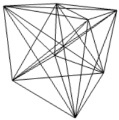
|
molecule
Generates a 3D molecular structure from the
given atom definitions and atomic links. The atoms are rendered as colored
spheres and the atomic links as lines in the usual way. Details:
The molecule entity allows to render a
molecular structure requiring only the symbols and 3D positions of the
involved atoms. In order to save computing resources the interpreter
renders the atoms in a special manner:
instead of generating real spheres, which requires too many computer
resources when several atoms are present, it generates signals
combining circular dots and a translucent image that represents the
sphere brightness. This strategy allows to save resources taking
advantage of the signals availability in LAI4D. Signals are 2D graphic
entities
rendered parallel to the projection plane and are scaled according to
depth in perspective projections. But the strategy
of using signals is not perfect. In general, the perspective projection
of a real sphere is not a circle but an ellipse, although a circle
located at the center of the sphere can
be a good replacement when the perspective projection is not very
forced. The brightness of a signal is not computed. The intersections of
the lines representing the atomic links with the surface of the spheres
representing the atoms also need to be simulated. The intersections
between spheres cannot be calculated. As a conclusion, the usage of
signals is an imperfect but reasonably good approach for representing
large molecules.
These are the members of the molecule entity:
- atoms: Mandatory. A container of atom entities. Each atom has the following members (the "type" member can be omitted):
- symbol:
A string with the standard scientific symbol of the atom. If the symbol
provided is not found in the internal atom library a default
radius of 159 pm and a default pink color will be assumed. Case
sensitive. For example: "H", "C", "Na", "N", "Fe"...
- point: A 3D point indicating the position of the atom with the
usual structure as for instance {{0.5}{30}{7.34}}. The recommended
measurement unit is pm (1e-12 m).
- radius: Optional. The radius of the sphere representing the
atom. If not provided then the interpreter will take the default value
for the atom's symbol from the internal library which is expressed in pm (1e-12 m).
- color: Optional. The RGBA color for the sphere representing
the atom. If not provided then the interpreter will take the default
value for the atom's symbol from the internal library.
- lines: A list of lines representing atomic links each of which is a set of indices that
points to the given atoms, as for instance {{0}{1}{2}{3}}. A line can
have any number of indices greater than one. If the "lines" member is not provided then no link is rendered.
- long links: If this member is non-zero then the atomic links are
represented from point to point without simulating the intersection
with the spheres.
- show symbols: If this member is non-zero then the symbol of the atoms are rendered as texts close to the center of the atoms.
The table of elements of the internal library is based on
Wikipedia data. The colors of common atoms are similar to those of other atom color charts and the radii are
expressed in pm (1e-12 m). It is recommended to express all the
geometric information of the molecule entity in pm, but as for the unit to use
is the user's decision.
|
Default atom data in the internal library:
|
| A | SYMBOL | NAME | R(pm) | COLOR |
|---|
| 1 | H | hydrogen | 53 |
|
| 2 | He | helium | 31 |
|
| 3 | Li | lithium | 167 |
|
| 4 | Be | beryllium | 112 |
|
| 5 | B | boron | 87 |
|
| 6 | C | carbon | 67 |
|
| 7 | N | nitrogen | 56 |
|
| 8 | O | oxygen | 48 |
|
| 9 | F | fluorine | 42 |
|
| 10 | Ne | neon | 38 |
|
| 11 | Na | sodium | 190 |
|
| 12 | Mg | magnesium | 145 |
|
| 13 | Al | aluminium | 118 |
|
| 14 | Si | silicon | 111 |
|
| 15 | P | phosphorus | 98 |
|
| 16 | S | sulfur | 88 |
|
| 17 | Cl | chlorine | 79 |
|
| 18 | Ar | argon | 71 |
|
| 19 | K | potassium | 243 |
|
| 20 | Ca | calcium | 194 |
|
| 21 | Sc | scandium | 184 |
|
| 22 | Ti | titanium | 176 |
|
| 23 | V | vanadium | 171 |
|
| 24 | Cr | chromium | 166 |
|
| 25 | Mn | manganese | 161 |
|
| 26 | Fe | iron | 156 |
|
| 27 | Co | cobalt | 152 |
|
| 28 | Ni | nickel | 149 |
|
| 29 | Cu | copper | 145 |
|
| 30 | Zn | zinc | 142 |
|
| 31 | Ga | gallium | 136 |
|
| 32 | Ge | germanium | 125 |
|
| 33 | As | arsenic | 114 |
|
| 34 | Se | selenium | 103 |
|
| 35 | Br | bromine | 94 |
|
| 36 | Kr | krypton | 88 |
|
| 37 | Rb | rubidium | 265 |
|
| 38 | Sr | strontium | 219 |
|
| 39 | Y | yttrium | 212 |
|
| 40 | Zr | zirconium | 206 |
|
| 41 | Nb | niobium | 198 |
|
| 42 | Mo | molybdenum | 190 |
|
| 43 | Tc | technetium | 183 |
|
| 44 | Ru | ruthenium | 178 |
|
| 45 | Rh | rhodium | 173 |
|
| 46 | Pd | palladium | 169 |
|
| 47 | Ag | silver | 165 |
|
| 48 | Cd | cadmium | 161 |
|
| 49 | In | indium | 156 |
|
| 50 | Sn | tin | 145 |
|
| 51 | Sb | antimony | 133 |
|
| 52 | Te | tellurium | 123 |
|
| 53 | I | iodine | 115 |
|
| 54 | Xe | xenon | 108 |
|
| 55 | Cs | caesium | 298 |
|
| 56 | Ba | barium | 253 |
|
| 57 | La | lanthanum | 159 |
|
| 58 | Ce | cerium | 159 |
|
| 59 | Pr | praseodymium | 247 |
|
| 60 | Nd | neodymium | 206 |
|
| 61 | Pm | promethium | 205 |
|
| 62 | Sm | samarium | 238 |
|
| 63 | Eu | europium | 231 |
|
| 64 | Gd | gadolinium | 233 |
|
| 65 | Tb | terbium | 225 |
|
| 66 | Dy | dysprosium | 228 |
|
| 67 | Ho | holmium | 159 |
|
| 68 | Er | erbium | 226 |
|
| 69 | Tm | thulium | 222 |
|
| 70 | Yb | ytterbium | 222 |
|
| 71 | Lu | lutetium | 217 |
|
| 72 | Hf | hafnium | 208 |
|
| 73 | Ta | tantalum | 200 |
|
| 74 | W | tungsten | 193 |
|
| 75 | Re | rhenium | 188 |
|
| 76 | Os | osmium | 185 |
|
| 77 | Ir | iridium | 180 |
|
| 78 | Pt | platinum | 177 |
|
| 79 | Au | gold | 174 |
|
| 80 | Hg | mercury | 171 |
|
| 81 | Tl | thallium | 156 |
|
| 82 | Pb | lead | 154 |
|
| 83 | Bi | bismuth | 143 |
|
| 84 | Po | polonium | 135 |
|
| 85 | At | astatine | 159 |
|
| 86 | Rn | radon | 120 |
|
| 87 | Fr | francium | 159 |
|
| 88 | Ra | radium | 159 |
|
| 89 | Ac | actinium | 159 |
|
| 90 | Th | thorium | 159 |
|
| 91 | Pa | protactinium | 159 |
|
| 92 | U | uranium | 159 |
|
| 93 | Np | neptunium | 159 |
|
| 94 | Pu | plutonium | 159 |
|
| 95 | Am | americium | 159 |
|
| 96 | Cm | curium | 159 |
|
| 97 | Bk | berkelium | 159 |
|
| 98 | Cf | californium | 159 |
|
| 99 | Es | einsteinium | 159 |
|
| 100 | Fm | fermium | 159 |
|
| 101 | Md | mendelevium | 159 |
|
| 102 | No | nobelium | 159 |
|
| 103 | Lr | lawrencium | 159 |
|
| 104 | Rf | rutherfordium | 159 |
|
| 105 | Db | dubnium | 159 |
|
| 106 | Sg | seaborgium | 159 |
|
| 107 | Bh | bohrium | 159 |
|
| 108 | Hs | hassium | 159 |
|
| 109 | Mt | meitnerium | 159 |
|
| 110 | Ds | darmstadtium | 159 |
|
| 111 | Rg | roentgenium | 159 |
|
| 112 | Cn | copernicium | 159 |
|
| 113 | Uut | ununtrium | 159 |
|
| 114 | Fl | flerovium | 159 |
|
| 115 | Uup | ununpentium | 159 |
|
| 116 | Lv | livermorium | 159 |
|
| 117 | Uus | ununseptium | 159 |
|
| 118 | Uuo | ununoctium | 159 |
|
|
DESCRIPTOR
|
PROTOTYPES
|
USAGE SAMPLE
|
RESULT
|
proto |
proto
|
|
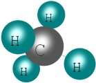
|
Library of ready-made useful entities
This section offers description and source
code for several already done entities which can be of use due to their
geometry or generation algorithm.
Spiral
Generates a 3D spiral centered at the origin
and oriented in the Z axis with the given height and the given initial
and final radii. Details:
The result of the algorithm is a "line"
entity that represents a 3D spiral. The vertices of the curve
are calculated with a simple polar algorithm in which the radius and
the Z coordinate vary linearly with the angle.
These are the elements that can be provided through the member "variable" with their positions:
- Total angle expressed in degrees. It can be negative. Mandatory.
- Initial radius. It can be negative. Mandatory.
- Final radius. It can be negative. Mandatory.
- Total height. It can be negative. Mandatory.
SOURCE
|
RESULT
|
|
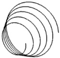
|
Multi copier
Generates a set of translated copies of the given entities according to the given set of vertices. Details:
The result of the algorithm is a group
entity (no type) whose "folder" member contains as many copies of the
given entities as vertices are provided. For each vertex the given set
of entities is copied, and for each copied entity a "translate" member is included with the corresponding vertex as value.
These are the elements that can be provided through the member "variable" with their positions:
- Container of entities to be copied. Mandatory.
- List of vertices destination of the copies. Mandatory.
In
the given sample the set of entities contains only a "box" entity.
The set of vertices has been obtained from a "sphere" entity after
converting it into a polynet.
SOURCE
|
RESULT
|
|
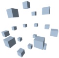
|
User interface
This section exposes the different functions offered through the LAI4D UI. Some of them are only available in design mode.
User input
Several functions require various input steps in which the user could provide:
- A selection of graphic entities generated by double clicking
over specific entities or by window capture for selecting a group of
entities completely contained inside the window area. See the "Selection
& visibility" section for more details.
- Texts or numbers typed in a text box. If the number entered is not an integer then the decimal separator shall be a dot.
- Point coordinates manually typed in a text box. LAI4D implements a parser
that tries to understand the data structure entered by the user
allowing a great flexibility in the input of coordinates. The user could
enter "
17.3,90,-10" or "17.3 90 -10" or "(17.3, 90, -10)" or even "{{17.3}{90}{-10}}"
and the parser will correctly extract the three coordinates. At least
one coordinate must be provided, the parser will automatically append
zeroes up to complete three coordinates.
- One or more points selected on screen that can be singular
points of entities, like vertices, or points located at the coordinated
planes. When the mouse is close to a singular point of an entity its coordinates and a
square mark are shown for highlighting that point and, if the user clicks
inside the square, the point is selected. When the user clicks over a
point that is not a singular point of an entity the selected point will
be that placed at the coordinated plane (XY, XZ, YZ) which is more
parallel to the viewport; therefore one of the three coordinates of the
point will be 0. An exception to this behavior can be found in the function "Modify vertex".
When the function in progress requests a user's input, an input area is
normally shown at the bottom of the viewport.
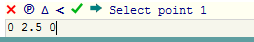
This input area can be
composed of:
- A cancel button (
 ):
If pressed then the function is cancelled. Some commands are
automatically recalled when done. This button finishes the loop and only
cancels the last call. ):
If pressed then the function is cancelled. Some commands are
automatically recalled when done. This button finishes the loop and only
cancels the last call.
- A pause button (℗/►): If pressed then the command is paused and the
user can change the camera configuration in the usual way. Once the
camera is configured the button can be pressed again in order to resume
the command. This function is typically used while selecting points in
the screen that are hidden for the current camera orientation.
- A delta button (∆): If pressed then the input of relative
coordinates is enabled. In this situation the on-screen selection of
points is ignored and the manually entered coordinates are treated as an offset with respect the last entered point.
- An angle button (<): If pressed then the input of polar
coordinates is enabled. The order of the coordinates must be: radius,
longitude, latitude (angles expressed in degrees). The coordinates left
blank by the right will be replaced by 0.
In this situation the on-screen selection of
points is ignored. If this button is combined with the delta button then
the manually entered coordinates are treated as an offset with respect
the last entered point.
- A finish button (
 ): It must be pressed when the user
does not want to enter more input items in the current input step. For example it can be used for
indicating the end of input when entering points for creating a
polygonal line or for indicating the end of the
entities selection step. ): It must be pressed when the user
does not want to enter more input items in the current input step. For example it can be used for
indicating the end of input when entering points for creating a
polygonal line or for indicating the end of the
entities selection step.
- A next step button (
 ): It must be pressed for
indicating that the current input step has finished and going into the
next input step. It is typically used for passing the value typed in the text box to the function and going into the next step. ): It must be pressed for
indicating that the current input step has finished and going into the
next input step. It is typically used for passing the value typed in the text box to the function and going into the next step.
- A text box: It is used for manually input of numbers or
coordinates. Most of the functions that require the input of points
allow either the selection of points on screen or the manual input of
coordinates. When the user types a value in the text box he must press
the finish or next step button in order to pass that value to the
function. If the value entered is not valid then the application warns
the user with an alert message and returns to the previous input status.
Apart from those inputs requested by the invoked function, there are
also other functions that offer in-place configurations. These functions
or configurable commands can be found under the "Tools menu" and present
their corresponding configurable options as child menu items of the
corresponding function menu item. The big difference between the
requested inputs and the in-place configurations is the fact that
in-place configurations are preserved between function calls so they
have to be edited only when necessary instead of having to be entered
each time the function is invoked.
On screen controls
The basic management of the widget is carried
out through a set of controls which are normally hidden until a user
action generates an event. These controls are organized in hiddable
groups placed at the corners of the widget. Additionally a long press
event performed over an entity will raise a set of context tools with
functions intended for that entity.
Top-left corner
 Shows the Tools menu which is the main access to the functions and options available in LAI4D.
 Opens a new browser window offering the available
sharing options. The goal of the "Share" functionality is to generate an
URL with the necessary start-up instructions for sharing the current
drawing directly as a link or as the "src" attribute of an IFRAME
element.
By default the generated URL is exactly the same as that used
for loading the widget. This default URL will usually indicate the
start-up instructions when the LAI4D widget is in reader mode. But when
LAI4D designer is being used the default URL could not contain any kind
of start-up instructions. Therefore you should save the changes in your
drawing with the function "Save server file" before trying to share it.
The application offers the following
configurable options for the generation of the new URL:
- Designer mode: If checked, the URL will point to the LAI4D
designer HTML page, else it will point to the LAI4D viewer HTML page.
- Include drawing source: If checked, the current drawing canonical
source is included in the start-up instructions. The user must take into
account that large drawings can result in too long URLs if this option is used.
- Include file origin if available: If checked, the last known file
origin is included in the start-up instructions. The LAI4D widget
internally maintains a variable containing the file origin initialized
when the widget is loaded and updated by the functions "Open server
file" and "Save server file".
- Include widget size: If checked, the size of the widget is included in the start-up instructions.
- Include current view definition: If checked, the current view
definition is included in the start-up
instructions. This allows to share the drawing using the current view
definition without modifying the own drawing source.
- Encode the resulting URL: If checked, the generated URL is encoded
with the standard encoding algorithm used for data passed through
the URL. The result is that several characters considered special are
replaced by a combination of "%" and a two digit hexadecimal number.
This option is rarely necessary but in some cases, when the loading of
the generated link or IFRAME code results in an error of the type "Bad
formed URI", it may solve it.
In the case of both the current source and the file origin are
simultaneously included in the start-up instructions, the source will
have priority over the file. See the "Widget initialization" section for
more details.
 Opens in a new browser window the help documentation.
 Opens in a new browser window the current drawing.
Top-right corner
 Increases
the zoom according to a preconfigured magnification factor. If a
long-press is applied then a progressive zoom is performed.
 Decreases
the zoom according to a preconfigured magnification factor. If a
long-press is applied then a progressive zoom is performed.
Bottom-right corner
Selector button that indicates whether the current projection is  parallel or  perspective and allows to change among them.
 Performs a zoom that allows to view the full scene regardless of the camera orientation.
 Shows the list of
issues (only when there is any). The list of issues will be normally populated by the problems
reported during the interpretation process of the source. See also the "Errors and problems" section.
 Changes to the
previous view stored in the view history. A new view is stored when the
view configuration of the camera is changed from the UI or when an
entity defining child entities (sub-drawings) is navigated with the function "Navigate into".
Bottom-left corner
 Shows the drawing canonical source in a non-editable text area.
 Opens the source editor. This component is intended to
offer the user an editable text area completely independent from the
drawing
where he can freely write new source code that can be committed upon
request. The component initially shows empty waiting for the user input
and it will retain its content when hidden. The component has the
following buttons at the title bar:
- A "get" (
 ) button that will replace the text area content by the current canonical source of the drawing. ) button that will replace the text area content by the current canonical source of the drawing. - A
"commit" (
 ) button that will try to interpret the content of
the
text area and then will try to render it replacing the current
canonical source of the drawing. The entire drawing can be cleared by
pressing the "commit" button when the text area is empty. Any error
during interpretation or
rendering will be notified as an issue. LAI4D is transactional so this
change is undoable pressing the "Undo" button in the tools menu. ) button that will try to interpret the content of
the
text area and then will try to render it replacing the current
canonical source of the drawing. The entire drawing can be cleared by
pressing the "commit" button when the text area is empty. Any error
during interpretation or
rendering will be notified as an issue. LAI4D is transactional so this
change is undoable pressing the "Undo" button in the tools menu.
- A "select node" (
 ) button that selects in the text area the source code
corresponding to the Gosyx node where the cursor is located. The cursor
location is assumed to be at the beginning of the selection range so
each time this function is called the selection range is extended to the
container node of the previous selection range. ) button that selects in the text area the source code
corresponding to the Gosyx node where the cursor is located. The cursor
location is assumed to be at the beginning of the selection range so
each time this function is called the selection range is extended to the
container node of the previous selection range.
The drawing source is a data structure that describes the drawing.
This data structure can contain graphic entities, view definitions,
configuration parameters, etc. arranged as a tree. The source is
considered canonical if all the data are encapsulated in a "drawing" entity
but the widget is able to accept non-canonical sources in order to
offer flexibility in the input. The user can write a drawing entity with
a folder member in which the graphic entities are described, or he can
directly write the content of that hypothetical folder member; both ways are valid.
The following example shows a canonical drawing source at the left side
and a non-canonical source at the right side defining the same graphic
entities:
{
  {type}
  {drawing}
  {folder}
  {
    {{type}{sphere}{radius}{100}}
    {
      {type}
      {box}
      {diagonal}
      {{50}{100}{50}}
      {translate}
      {{100}{0}{0}}
    }
  }
}
|
|
{{type}{sphere}{radius}{100}}
{
  {type}
  {box}
  {diagonal}
  {{50}{100}{50}}
  {translate}
  {{100}{0}{0}}
}
|
|
Indeed, when a non-canonical source is committed LAI4D automatically
creates an empty drawing entity and then inserts the non-canonical source
into the folder member of that empty drawing. The user will normally
write non-canonical sources although the drawing entity may be necessary
in order to edit specific members like "background color" only present in the drawing entity. Since the
"folder" member of a drawing entity can contain any type of entity,
even view definitions, the user can also include view definitions in the
non-canonical source.
The source editor may not be the most comfortable way for editing an
already existent drawing composed of many entities. See the "Tree
explorer" and "Explore as a tree" sections for more details.
 Reinterprets the drawing source and renders again
the drawing resetting the options. The modifications of the source and
the UNDO history are respected. This function is useful for returning
the widget to a known initial status preserving the design changes.
Context tools
When a long press event occurs over a graphic
entity a set of buttons with context tools is shown allowing to perform
the following operations on that entity:
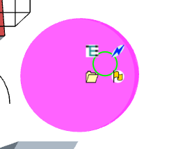
Explore as a tree
 The source of the entity is shown in the Tree explorer. In design mode this
allows to directly edit the source of the entity. See the "Tree
explorer" section for more details.
Navigate into
 If there are children in the graphic entity then the
widget navigates into the entity allowing to explore them. The children
are
found in the "folder" member. In order to perform a backward navigation
use the "Previous view" function. See the "Sub-drawings" section for
more
details.
Navigate link
 If
the entity has a link then it is navigated as a web link opened in a
new window. The link is defined in the "link" member.
View attached user data
 If user data is available in the entity then its content is shown. The user data is defined
in the "user data" member. It can be a simple text or it can be any possible data structure.
Dynamic zoom
Through mouse wheel events the user can make a general exploration of the model
space. Each event produces a combination of a zoom increment plus a
camera movement. When the wheel is rolled up a zoom-in is performed
while the camera is displaced towards the area pointed by the mouse.
When the wheel is rolled down the zoom and camera displacement are inverse.
To use the dynamic zoom is a comfortable way of exploring a wide scenario
without the need of calling several times to different camera
configuration buttons.
Tools menu
The Tools menu is the main access to the LAI4D
functionality. The functions are arranged in a tree view layout that is shown when
the user presses the "Tools" button placed within the group of on screen
controls at the top-left corner. The menu items can have different purposes:
- Group: It is a simple container of other menu items with a descriptive text.
- Button: It is printed in dark red and invokes the corresponding
function when receives a click event. As explained in the section "User
input" it can contain more menu items intended for configuration.
- Text input: Allows the input of a number or a text piece. Used for configuration.
- Check boxes: Allows to check or uncheck an option. Used for configuration.
- Drop-down lists: Allows to select an option among a set of options. Used for configuration.
Undo
 Undoes the last change in the drawing source and repaints the scene.
Redo
 Redoes the last undone change in the drawing source and repaints the scene.
Design
 Opens the current drawing in design mode in a new
window. If this function is invoked from design mode then the new window
will show the drawing in its current state taking into account the
possible changes performed.
View control
 The full configuration of the view can be achieved
through the use of the "view" entity. The functions described in this
section cover the more commonly demanded view operations not available
in the "On screen controls".
Prompts the user to select two points on the screen and performs zoom to the selected area.
Performs a zoom extent and sets the camera orientation according to the selected predefined view.
Moves the camera towards the target point.
Moves the camera away from the target point.
Prompts the user to select a point in the scene and modifies the view definition so it becomes the new target point.
Prompts the user to select a set of entities and focus the view on it.
If
checked then the camera can only be oriented in latitude and longitude,
the inclination becomes 0. This option provides the sensation that
the Z axis is vertical regardless of the camera orientation.
File
Offers different storage and retrieval options.
Browser's storage
Opens
or saves a drawing file in the local storage of the browser. At the
same time it allows to delete already existent files. Browser's local
storage allows web applications to store data in a persistent way in the
client's browser even if it is closed or the page is reloaded.
Browser's storage
should be seen as an utility for helping in the edition process of
complex drawings, not as a permanent means for preserving drawing files.
Not all web browsers allow the access to the local storage while offline.
The files saved in the browser's
storage will remain visible to any user that navigates the same web page
from where the file was saved. Therefore the user should clean the browser's storage if he works in a shared computer.
|
Open server file
Retrieves
a file stored in the LAI4D server and tries to interpret and render its
content. The user must enter the name of the file as it was returned by
the server when the file was stored. This option only works when the
LAI4D widget has been loaded directly from the LAI4D official site.
This is a free service offered by
LAI4D. The stored files are uploaded by anonymous users and LAI4D does
not offer any kind of warranty over their content. Detected abuses can
be notified to LAI4D. If the user does not agree
with the stated terms of service then it must not be used.
|
Save server file
Stores
the current drawing in the LAI4D server. The user must enter the file name
desired using only alphanumeric and underscore characters. The
name can be up to 32 characters in length. After storage the server will
return the definitive name of the file composed of the provided name
plus a keyword randomly generated by the server. The user should keep
safe this definitive name in order to be able to retrieve the file in
the future. The stored files cannot be overwritten. The file size allowed for this service is 500 Kb approximately.
This saving option is intended for those people that do not have their
own web space and want to share the drawing through the Internet. For
temporary saving of drawings the user
should use the function "Browser's storage". For testing purposes use
names beginning with "TEMP"; these files will be periodically removed
from the server. Remember that you can store your drawing file in your
own web space without size limits and then open it using its absolute
URL. See also the "Publishing
LAI4D drawings" section.
This is a free service offered by
LAI4D. The stored files will be publicly available and any user with
the file name will be able to access it in read-only mode since no
logging is required. The integrity or accessibility of the files cannot
be warranted indefinitely. If the content of the file is valuable for the
user then to make a backup copy is recommended. Files without activity
for a long period of time or with malicious content can be deleted. The
author of the file uploaded renounces to any exclusive right over his
creation that becomes of public domain. If the user does not agree with
the stated terms of service then it must not be used.
|
Local drive
Opens
a local L4D file and tries to interpret and render its content. The
real file extension is not relevant. Local files can also be loaded
through a drag & drop operation.
Allows to save the current drawing as a L4D file clicking on the generated hyper link.
Allows to save a snapshot of the current view as a PNG image file clicking on the generated hyper link.
Import/Export
Imports a drawing from a DXF file. The
following entity types are imported: lines, 2D and 3D polylines,
circles, arcs, splines (only support points), 3D meshes. Styles and
block references are not imported. Most of the not imported original DXF
data is left in the resulting drawing as non-standard members or as
entities without type. Only ASCII format is supported.
Exports the entities currently rendered to a
DXF file. The program processes the entities and generates the
corresponding DXF source. Then shows a hyper link to the generated DXF
source that can be saved as a text file. Only geometry is exported,
signals are ignored.
Imports a drawing from a PLY file. The
following element types are imported: vertex (with optional red, green,
blue and alpha properties), edge, face. Only ASCII format is supported.
Exports the entities currently rendered to a PLY file. The program processes the entities and generates the
corresponding PLY source. Then shows a hyper link to the generated PLY
source that can be saved as a text file. Geometry is always exported, colors are exported if defined as vertex colors,
signals are ignored.
Imports a drawing from a OBJ file. The
following element types are imported: vertex, line, face. Only ASCII format is supported.
Exports the entities currently rendered to a OBJ file. The program processes the entities and generates the
corresponding OBJ source. Then shows a hyper link to the generated OBJ
source that can be saved as a text file. Only geometry is exported,
signals are ignored.
Imports a drawing from a STL file. Each solid becomes a new polynet. ASCII and binary formats supported.
Exports the entities currently rendered to a STL file. The program processes the entities and generates the
corresponding STL source. Then shows a hyper link to the generated STL
source that can be saved as a text file. Only surface geometry is exported,
signals are ignored.
New drawing
Opens an empty drawing in design mode in a new
window.
Options
 Allows
to configure rendering and behavior options and parameters. Most of
these options cannot be configured through the drawing source so they
are offered for testing purposes in design mode.
Show reference system
Shows the
3 axes of the scene reference system with the current orientation in a small
area at the bottom-right corner. The X axis is painted in blue, the Y axis in green and the Z axis in red.
Draw lines
If checked then the lines of the drawing are painted.
Draw faces
If checked then the faces of the drawing are painted.
Draw signals
If checked then the signals of the drawing are painted.
Stroke faces
If checked then the border of all the faces is stroked.
Apply lighting
If checked then the brightness of the faces is calculated and rendered.
Edition optionsIf
checked then indicates that the transformation commands (scale, rotate,
move...) must generate transformation entities instead of modifying the
'transform' and 'translate' members. It is useful in case there is
interest on configuring that kind of transformation entities.
If
checked then indicates that the copy commands (copy, cartesian...) must
clone the original entities instead of creating inheritance resolved
copies. This option is normally checked because in this way the copies
keep the inheritance when the original entities use inheritance. If
unchecked then the copying process
creates new entities after resolving inheritance in the original
entities. To uncheck this option may be useful when the copies are
undergoing further edition processes for which the inheritance is not
convenient. The member "name" is never copied and the "inherit" member
is neither copied when this option is unchecked.
Design assistant options
Perform
Optical Character Recognition for measures painted in the sketch area.
When this option is enabled the design assistant tries to match the
recognized numbers to the painted strokes and to resize the obtained
geometry. If this option is disabled then the possible numbers painted
will be considered normal strokes.
Try
to imagine hidden faces in 3D hypothesis. When this option is enabled
the design assistant is able to imagine the hidden faces which close the
3D geometry in some cases.
The
recognized numbers correctly assigned to the geometry are painted in
the hypothesis close to the element they were assigned to. These
assigned measures represent the successful resizing of the correspondent
elements.
Print non-assigned measures The
recognized numbers that could not be correctly assigned to the geometry
are painted in the hypothesis in a light color. This option is useful
to highlight numbers which were correctly recognized by the OCR and
linked to a segment but could not be properly assigned to the geometry.
Geometric hypothesis as source Show
geometric hypothesis as source instead of as graphic. The entities
corresponding to a geometric hypothesis (normally a polynet) will be
shown as a Gosyx source code. Useful for low resource computers.
Show the initial raw hypothesis. This almost unprocessed 2D hypothesis is not normally useful so it is hidden by default.
Highlight face borders in 3D hypothesis.
Inverse depth interpretation
By checking this option the design assistant changes the depth interpretation criterion when generating 3D hypothesis.
Advanced rendering options
If checked then performs hiding calculation according to depth. This
must not be confused with the hiding of entities through the usage of
the "ignore" member.
If checked then signal elements are scaled according to depth as any other 3D entity in the scene.
Ignore WebGL vertex colors If checked
then vertex colors are ignored in the entities where they are defined
using therefore the face or line colors. Only
considered in WebGL rendering context.
If checked then canvas 2D rendering context
is forced even if WebGL is available. If
changed then a repaint is performed to see the effects.
Number
that indicates how many
segments should have the polygon that represents a circle. It is used
for deciding the mesh density of a curved entity (line or surface) when
it is converted
into a polynet. If changed then a repaint is necessary to see the
effects. High values of this parameter will result in longer rendering
times when curved entities are present.
Behavior options
Number indicating the
standard geometric tolerance. It is used in several geometric
operations for deciding equality between points or for evaluating proximity criteria.
Indicates the preferred serialization mode of Gosyx nodes in controls like the Tree explorer. There are three modes:
- Single line: The whole node is serialized in a single text line.
- Indent: Each child node of the current node is printed in a new
line with the corresponding indentation according to the nesting level.
- Table: Almost equal to the 'Indent' mode but when a compound
node is composed only of single nodes then this node is printed in a
single line. This is the default mode and normally the most comfortable.
If checked then the on-screen point selection will find entity vertices.
Quick find singular points
If checked then the on-screen point selection will find entity singular points like centers or control points.
Quick find graphic traces
If checked then the on-screen point selection
will find graphic trace points. The auxiliary geometries painted while
creating an entity are considered graphic traces.
If checked then indicates that some UI visual effects can be performed as an animation.
Selection & visibility
Graphic selection
Select entities by double click or by window capture. The window
selection selects all entities completely inside the window. The user
must press the "end" button to finish the selection process.
Select auxiliary entities
Appends to the current selection all entities with the label
'auxiliary'. After that the auxiliary entities can be easily hidden or
deleted.
Invert selection
Inverts the current selection.
Clear selection
Clears the current selection.
Selection source
Shows the source of the selected entities.
Hide selection
Hides the
selected entities. The member "ignore" with a value of 1 will be
appended to the selected entities so they will be ignored by the
interpreter.
Unhide all
Unhides the hidden entities. All entities of the drawing source will be scanned removing the member "ignore" if present.
Edition
 Contains all the functions intended to create or edit the drawing entities.
Create entities
Default properties
 Allows to configure the default properties to be assigned to new entities:
- Color for faces: Used for the member 'face color'. Opens the
'Color generator' tool allowing to select or edit a color definition.
When the configuration ends the 'Done' button must be pressed in order
to commit the changes. If the text input field of the 'Color generator'
is left blank then no color is set.
- Color for lines: Used for the member 'line color'. Opens the 'Color
generator' tool allowing to select or edit a color definition. When the
configuration ends the 'Done' button must be pressed in order to commit
the changes. If the text input field of the 'Color generator' is left
blank then no color is set.
- Label as 'auxiliary': Indicates whether the generated entity must be labeled as 'auxiliary'.
Sets
default properties to the selected entities. This command is useful to
change colors and other properties to existent entities. If no entities
are selected then the user is prompted to select them.
Create line
Creates
a linear entity from the entered set of vertices and
considering the given command configuration. The command offers the
following in-place configurations:
- desired result type: Indicates the type of the generated entity. It is a drop-down list with the following options:
- line: The entity type will be "line" and will represent the entered polygonal line.
- curve: The entity type will be "curve" and will touch the entered vertices.
- polynet: The entity type will be "polynet" and will represent the entered polygonal line.
- entity closed: Indicates whether the generated entity must be closed.
Create regular polygon
Creates
a "polygon" entity at the XY plane from the entered center, radius
point and number of
sides. The polygon is circumscribed to a circle whose radius is the
distance between the 2 points entered but measured in the XY plane.
Create face
Creates
a face entity from the entered set of vertices and
considering the given command configuration. The command offers the
following in-place configurations:
- stroked face: The entity type will be "polynet" and will have a
face and the corresponding bounding line according to the entered
vertices.
Create box
Creates
a box entity from the entered pair of points.
Create regular polyhedrons
Creates the selected regular polyhedron from the entered center and radius point.
Create text signal
Creates
a polynet entity with text signals and
considering the given command configuration. For each signal the user
must select the anchor point and the corresponding text string. The text
signals allows several configurations. The text color is determined by the
"Color for lines" configured in the "Default properties". See the
"signal text" section for more details. The command offers the
following in-place configurations:
- font size
- font family
- font weight
- font style
- offset X
- offset Y
- draw polynet line: Draw a line joining the anchor points. By default the polynet only shows the signals.
For each entered signal the in-place configurations can be changed what results in different attributes for each one.
Circles and arcs
Includes
a set of commands that allow the creation of circle entities from
different inputs. Depending on the selected option, the circle can be
placed at the XY plane or freely arranged in the 3D space. Some options
allow to create an arc instead of a complete circle:
- XY: circle from center + radius.
- XY: circle from center + point + optional angle for arc.
- XY: circle from 2 points of diameter.
- 3D: circle or arc from 3 points.
Spheres
Includes
a set of commands that allow the creation of sphere entities from
different inputs:
- Sphere from center + radius.
- Sphere from center + point.
- Sphere from 2 points of diameter.
- Sphere from 4 points.
Cylinders and cones
Includes
a set of commands that allow the creation of revolved entities representing cylinders or cones:
- Cylinder from axis + radius.
- Cylinder from axis + point.
- Cone from axis + radius. The vertex of the cone is the second point of the axis.
- Cone from axis + point. The vertex of the cone is the second point of the axis.
- Cone trunk from axis + 2 radii.
- create bases: Indicates if the generated entity must be closed with circles.
Create revolved surface
Creates
a revolved entity from the entered profile and axis. The points of the
profile are interpolated to generate a curve with the same algorithm as
the "curve" entity so it does not need to be planar. The command prompts
the user to decide if the entered profile must be closed.
Create pipe
Creates
a pipe entity from the entered profile and guideline. The points
of both the
profile and guideline are interpolated to generate a curve with the same
algorithm as
the "curve" entity so they do not need to be planar. The command prompts
the user to decide if the entered profile or guideline must be closed.
The profile is assumed to be referenced to the first point of the
guideline and to the tangent to the guideline at that point. Extruded
surfaces can be generated using a straight segment
as guideline.
Create patch
Creates
a patch entity from the entered ring sides. The user must enter the 4
sides of the ring in sequential order. Each side needs at least 2 points. Since the ring must be closed,
the command automatically assumes that each side begins with the last
point of the previously entered side. If the last point of the last side
does not coincide with the first point of the first side then the
command automatically appends a copy of that point to the last entered side.
Create mesh
Creates
a mesh entity from the entered rows of points. At least 2 rows are
necessary and each row needs at least 2 points. All rows will have the
same number of points. After entering the rows the command asks the user the following options:
- Close the mesh in the 's' direction (rows)?: If accepted then the surface will be closed in the direction of the rows.
- Close the mesh in the 't' direction (columns)?: If accepted then the surface will be closed in the direction of the columns.
- Make the mesh smooth?: If accepted then the generated surface will be smoothed.
Copy entities
⧉ Copies the
selected entities to a new location in the scene. If no entities are
selected then the user is prompted to select them. The copying process is affected by the configuration option "Clone on copy".
Move entities
 Moves the
selected entities from one point to other. If no entities are selected
then the user is prompted to select them. See also the "Generate transformations" configurable option.
Delete entities
 Deletes the selected entities. If no entities are selected then the user is prompted to select them.
Clear drawing
 Deletes all entities. This change is undoable.
Transformations
Rotate entities
Rotates the
selected entities the entered angle around the selected axis. If the
axis' second point is not provided then it is assumed that the rotation
axis is parallel to the Z axis {{0}{0}{1}}, as if it were a 2D rotation
in the XY plane. If no
entities are selected then the user is prompted to select them. See also the "Generate transformations" configurable option.
Scale entities
Scales
the selected entities according to the entered origin and scale factor.
If no
entities are selected then the user is prompted to select them To
perform a scaling by pairs of points see the command "Align entities".
See also the "Generate transformations" configurable option.
Symmetric entities
Changes the selected
entities to their symmetric. The symmetry can be with respect a point if
one point is entered; with respect a straight line if two points are
entered; or with respect a plane if three points are entered. If no
entities are selected then the user is prompted to select them. It is
important to notice that the original entity is transformed to obtain
its symmetric. The
program asks the user for confirming whether he wants to preserve as a copy the
original entities or not. See also the "Generate transformations" configurable option.
Align entities
Aligns
the
selected entities according to the three pairs of points entered. The
alignment involves a translation, a rotation and an optional scaling:
- The first pair of
points defines the translation from an origin point to a destination
point.
- After that, the selected entities are rotated so as the vector
formed by the origin and the first point of the second pair gets aligned
with the vector formed by the destination and the second point of the
second pair. If the user confirmed the scaling option then these two
vectors are also used to calculate the uniform scaling factor to apply.
- At the same time, the vector formed by the origin and the first point of the third pair
gets aligned with the plane formed by the destination, the second
point of the second pair and the second
point of the third pair.
Only the first pair of points is mandatory. If no
entities are selected then the user is prompted to select them. See also
the "Generate transformations" configurable option.
Transform entities
Configures a generic affine transformation according to the four pairs
of points entered and applies it to the
selected entities. The generic affine transformation involves a
translation and a change from one basis to other one. Each
basis is defined by four points: one origin and the
three edges of the three vectors representing the axes. Each
pair of points entered defines the correspondence between the points
in both bases. For example, the first pair of points defines
the correspondence between the origins, the second pair of points
defines
the correspondence between the edges of the first axis, and so on.
Only the first pair of points is mandatory. Depending on the number of pairs of points provided the operation can be:
- simple translation
- translation + rotation + elongation along a line
- translation + plane alignment + planar deformation
- translation + complete transformation
If the bases present linear combination the operation may be unfeasible. If no
entities are selected then the user is prompted to select them. See also the "Generate transformations" configurable option.
See here an example of how this command is applied to transform a wired cube using a tetrahedron as target basis:
Initial situation
|
|
Transformed cube
|
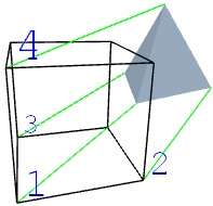
|
|
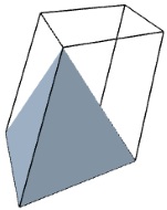
|
Cartesian array
Generates
a 3D cartesian array layout copying the selected
entities according to the entered array dimensions and cell size. If no
entities are selected then the user is prompted to select them. The
copying process is affected by the configuration option "Clone on copy".
Polar array
Generates
a 3D polar array layout copying and rotating the selected entities
according to the entered axis and step definition. The user can provide
the following data:
- Axis: Two points defining the rotation axis of the layout. If the
axis' second point is not provided then it is assumed that the rotation
axis is parallel to the Z axis {{0}{0}{1}}, as if it were a 2D rotation
in the XY plane
- Steps: An integer value indicating the number of
elements of the array, including the original one. It must be greater
than 0.
- Angle step: Angle increment expressed in degrees corresponding to each step.
- Height step: Height increment along the axis corresponding to each step. This argument allows to
generate solenoidal distributions.
- Base: An optional 3D point considered as base point for the set of
entities to be copied. If provided then the elements are translated to
the destination points of the array. If omitted then the elements will
be rotated as they are copied according to the "angle step" argument.
If no
entities are selected then the user is prompted to select them. The
copying process is affected by the configuration option "Clone on copy".
Project to 2D
Replaces
the selected entities by polynets with the corresponding 2D projection
in camera coordinates. The selected entities are removed and the new
entities are appended to the drawing not occupying the old place in the
tree of the selected entities. The result is a completely planar set of
polynets
placed at the XY plane (Z = 0). This means that the result should be
viewed using the predefined view configuration "Plan: XY ∟ +Z". Camera
coordinates are measured in pixels with the origin at the center of the
viewport. If no
entities are selected then the user is prompted to select them. See also
the command "Show projected vertices".
Advanced edition
Modify vertex
Allows
to modify the vertices of the selected entity if it is of type 'polynet', 'line', 'face', 'curve', 'mesh' or 'patch'. If no
entities are selected then the user is prompted to select one. An entity can
be converted into polynets
with the command 'Replace by polynets'.
Once the entity is selected the program requests a vertex to be
modified. After selecting the vertex the user must enter the new
coordinates for the vertex or must select a new location for it on the
screen. If this last approach is used, the new location could coincide
with another existent point, in which case the new coordinates
will be those of the selected existent point. But if that is not the
case
then the program computes the new position assuming that the original
point is moved in a plane parallel to the coordinated plane (XY, XZ, YZ)
which is more
parallel to the viewport; therefore one of the three coordinates of the
point will not be changed (that corresponding to the axis more
perpendicular to the viewport). This strategy is very useful when
applying manually fine corrections to a vertex position.
Replace by polynets
Replaces
the
selected entities by the polynets resulting from their interpretation.
The selected entities are removed and the new entities are appended to
the drawing not occupying the old place in the tree of the selected
entities.
This command is useful due to the fact that some operations only work on
source entities when they are polynets. Another important application
of this command is the obtaining of a resolved standard geometry whose
definition is independent from the specific generation algorithm of the
replaced entity type or from the Tessellation parameter. If no
entities are selected then the user is prompted to select them.
Batch modify
Allows
to modify, remove or add members to the selected entities in batch
mode. The function compiles all members not inherited of the selected
entities and shows a tree view allowing their edition. The "folder"
member of an entity is not compiled but it do is searched looking for
child entities to scan. The value node of each compiled member is
initially shown empty. When the changes are committed, the selected
entities are modified in the following ways:
- Modify member values: If the new value of a member is not empty
then all entities that originally declared that member will be updated
to the new value.
- Remove members: If a member (key and value nodes) has been
removed then all entities that originally declared that member will be
updated removing the member.
- Append new members: If a new member (key and value nodes) has
been added then all entities will
be updated adding the new member, even if its value is empty.
If the user wants to set the value of a member for all selected entities
regardless of whether it is originally declared or not, then the
recommended approach is to remove the member in a first call to this
function and then append it as a new member with its new value in a second call.
If no
entities are selected then the user is prompted to select them.
Copy properties
Copies
the configured members from the selected source entity to the selected
set of target entities. The command offers a set of in-place
configurable check boxes for indicating the members that can be copied.
The function will only work with the members whose check box is marked,
the rest will be ignored. Only members directly declared (not inherited)
on the entities, source or target, will be handled. For the configured
member names:
- Members present in the source entity will be
copied to the target entities replacing the previous member values if any.
- Members not present in the source entity will be removed from the target entities if present.
Component operations
For
each selected entity generates a polynet with one closed line for each
face definition and one face for each line definition in the entity.
Useful command for extracting lines or faces from entities where they
are not defined. If no
entities are selected then the user is prompted to select them.
Compiles
all the line definitions of the selected entities and tries to
concatenate them creating a single polynet with the resulting new lines.
Useful command for generating a single line from a group of different
connected lines. The
original entities are removed. If no
entities are selected then the user is prompted to select them.
Replaces
the selected entities by a single polynet with their optimized wire
representation. The selected entities are removed and the new entities
are appended to the drawing not occupying the old place in the tree of
the selected entities. If no
entities are selected then the user is prompted to select them.
Original entity
|
|
Wire representation
|

|
|
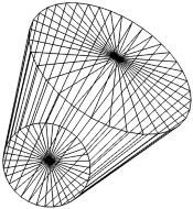
|
Requests
the user to select surface entities and returns a polynet with the
contour bounding the surfaces. The command accepts any
type of entity but only surfaces are considered. The selected entities
are removed and the new entities are appended to the drawing not
occupying the old place in the tree of the selected entities. The
contour will be composed of closed lines.
The function considers any face edge connected only to one face as part
of the contour. If the user wants to obtain the multiple contour of a
face
defining holes instead of its single contour then he should consider to
explode the face into triangles before applying this command. Correctly closed
surfaces don't
have contour. If a valid contour is not found then the command is
cancelled raising a warning message.
The
original entities are removed. If no
entities are selected then the user is prompted to select them.
The user should consider to use the command "Merge entities" before this
one. The influence of this option is very important. The algorithm
checks the face connections by comparing the vertex indices of the face
edges. Two faces may be topologically connected through a shared edge,
but if that edge is defined by different indices in both faces then the
algorithm won't consider it a connection. After a merging this problem
should get fixed. However, this behavior is optional because it may not
be desirable in all circumstances.
Replaces
the
selected entities by a single polynet with all the faces, lines and
signals; non
geometric members are ignored including colors and folder. Any
possible transformation is resolved. The selected entities are removed
and the new entities are appended to the drawing not occupying the old
place in the tree of the selected entities. The command offers the
following in-place configurations:
- merge vertices: The vertices
are merged according to the configuration parameter "Tolerance".
- remove coincident or invisible faces and lines: If a face or line
coincides topologically with other one then it is discarded. If a face
or line has all its vertices equal then it is discarded. This option only works if vertices are merged.
- preserve signals: If this option is unmarked then the signal
definitions of the selected entities will be lost after the merging
process.
If no
entities are selected then the user is prompted to select them.
Replaces
the
selected entities by a group of polynets, one for each line or face
defined in the selected entiies; non-geometric members are ignored
including signals and folder. Each generated polynet will have only the
necessary vertices. The selected entities are removed and the new
entities are appended to the drawing not occupying the old place in the
tree of the selected entities. The command offers the
following in-place configurations:
- divide faces into triangles and lines into segments: Each face
definition is replaced by the result of its triangulation and each line
definition is replaced by its segments.
- create 'face' and 'line' entities instead of polynets.
If no
entities are selected then the user is prompted to select them.
This
command merges all the entities of the drawing into a reduced set of polynets in order to improve the performance of the
widget when using WebGL. This operation is useful for complex drawings
composed of many entities because it transfers part of the rendering
work load from the JavaScript side to the WebGL side (when WebGL is in use).
The current entities are replaced by a few polynets and non-graphic
information is lost including attachments. For that reason this command
should be only used when the design is finished. Obviously the resulting
entities can be edited again in the usual way. The result contains the following entities:
- A polynet with all the signal definitions.
- A polynet with all the line definitions.
- A polynet with all the face definitions using the "face curved" member.
- A polynet with the rest of face definitions.
Its worth to mention the
following process details:
- The colors will be redefined only using the "vertex colors" member.
- Line widths will be ignored.
- Invisible entities will remain unchanged in the drawing.
Geometric calculations
Generate entities from geometric calculations.
Generates a line between the two selected points divided into as many equal segments as the entered number of divisions.
Requests
the user to select a single point and a pair of points representing a
straight line and generates the segment corresponding to the minimum
distance between them. The calculation is not possible with a line
defined by two coincident points.
Requests the
user to select two pairs of points representing two straight lines and
generates the segment corresponding to the minimum distance between them.
The calculation is not possible with a line defined by two coincident
points or with parallel lines. This operation is very useful for finding the intersection of two 3D lines.
Requests
the user to select a single point and three points representing a plane and generates the segment corresponding to the minimum
distance between them. The calculation is not possible with a plane
defined by aligned points.
Calculates
the side lengths and angles not provided of a triangle and passes it to
the design space. The command shows a form with 6 numeric fields for
the 3 side lengths and the 3 angles. At least one length must be
provided. The number of lengths plus the number of angles must be at
least 3. The calculation does not validate the entered
values so it is not convenient to provide more data than that strictly necessary. These are the recommended combinations:
- 3 lengths.
- 2 lengths, 1 angle.
- 1 length, 2 angles.
By pressing the "Solve triangle" button the triangle is solved and the
blank fields are completed if possible. By pressing the "Pass triangle
to drawing" button the triangle is solved if possible, and in case of success the
triangle is passed to the design space as a polynet with the vertex α
placed at the origin and the side C placed along the X axis. If the calculation is not possible then a warning message is
shown.
Calculates
the vertices of a tetrahedron from the set of segment lengths and
passes it to the design space. All segment lengths must be provided. By
pressing the "Solve and pass tetrahedron to drawing" button the
tetrahedron is solved if possible, and in case of success the
tetrahedron is passed to the design space as a polynet. The four
vertices are placed according to the following:
- A: Base point at the origin (0,0,0).
- B: Base point at the plane XY (x,y,0).
- C: Base point at the X axis (x,0,0).
- D: Vertex with positive Z (x,y,z).
If the calculation is not possible then a warning message is
shown.
Interference operations
Perform operations from the interferences between entities.
Requests
the user to select entities and returns the line and
surface fragments resulting from their intersections. The command
accepts any type of entity but signals are ignored. The following
intersections are calculated: line-line, line-surface, surface-surface.
Only intersections between different entities are considered. Surfaces don't need to be solid or closed.
Calculations that involve geometries with a huge number of segments or
faces (organic surfaces for instance) can take a long time.
After calculating intersections, line and surface fragments are
returned in separated polynets regardless they were originally defined
within the same entity. The resulting entities preserve the following
members from their original counterparts: line width, line color, face
color, face curved, fill, stroke, labels. The
original entities are removed. If no
entities are selected then the user is prompted to select them.
Example of an intersection between a box and an sphere. The image shows the 4 resulting fragments separated:
Requests
the user to select a set of entities and a plane defined by 3 points
and returns the line and
surface fragments resulting from cutting the entities by the plane. All
the process is carried out in the same way as the command "General
intersection".
Cut-line between surfaces Requests
the user to select surface entities and returns the
cut-line resulting from their intersections. The command accepts any
type of entity but only surfaces are considered. The resulting lines are encapsulated in a polynet.
Only intersections between different entities are considered. Calculations that involve geometries with a huge number of
faces (organic surfaces for instance) can take a long time.
The
original entities are removed. If no
entities are selected then the user is prompted to select them.
Drawing metadata
Generates
or updates in the current drawing entity the values for the drawing
metadata members. See also the "drawing" entity for more details.
Sets 'view' member in the drawing with the current view configuration.
Selects and sets 'background color' member in the drawing.
Sets
'flags' member. The flags included in the value of this member will
depend on the status of different configurable options. See the "flag"
member of the "drawing" entity for more details.
Set version and authoring Sets version and authoring related members.
Auxiliary constructions
Appends to the drawing graphic elements typically used as reference.
Generates three segments at the axes X, Y, Z with the given lengths and connected at the origin. The command offers the
following in-place configurations:
- length of the X axis.
- length of the Y axis.
- length of the Z axis.
- also negative axes: If checked then not only the positive side of the axes but also the negative one will be generated.
This construction shows the position of the origin of coordinates and
can be very useful as a reference for generic transformations.
Generates
a square grid in the coordinated planes with the given side length and number of
divisions. The grid is built touching both axes. The
command offers the
following in-place configurations:
- side length.
- side divisions: Must be a positive integer.
- XY plane: The grid is generated for this coordinated plane. Marked by default.
- XZ plane: The grid is generated for this coordinated plane.
- YZ plane: The grid is generated for this coordinated plane.
Extract information
 Contains functions for extracting useful information from the existing entities.
Point coordinates
Show the coordinates of the selected point. The information includes
scene coordinates, camera coordinates and vertex ID in the corresponding
polynet.
Measure distance
Show the distance between two selected points. Additionally the coordinates of the middle point are also shown.
Measure angle
Show the angle
formed by three selected points expressed in degrees in the range [0º,
180º]. The second point is the angle's vertex.
Measure polygon
Prompts the user to select a set of points and shows a summary with the following information:
- Total length.
- Center of gravity of the polygonal line.
- Assumed planar area of the polygonal line. The assumed planar area is the area of the triangulation of the polygon
resulting from closing the polygonal line.
- Center of gravity of the area.
- The result of triangulation
is also shown (each triangle is a set of three indices pointing to vertices).
Physic properties
Prompts the user to select a set of entities and shows a summary for each one of them with the following information:
- Polynet number. The interpretation of the navigated entity results
in a list of polynets. This number is the index of the corresponding
polynet inside that list.
- Bounding box. Two points corresponding to the diagonal of the container box.
- Total length of the defined lines.
- Center of gravity of the lines.
- Total area of the defined faces. Faces are triangulated before this calculation.
- Center of gravity of the area.
- Total volume bounded by the defined faces. Faces are triangulated
before this calculation. The faces must be connected among them through
shared vertices defining one or more closed polyhedrons; in other case
the result may have no sense.
- Center of gravity of the volume bounded by the defined faces.
At the end of the report the aggregated properties of the selected entities as a compound are shown too.
Advanced
Prompts the user to select a set of entities. The topology of each
entity is analysed checking connections between faces. At the end shows a
summary for each one of them with the following information:
- Polynet number. The interpretation of the navigated entity results
in a list of polynets. This number is the index of the corresponding
polynet inside that list.
- Well oriented: True if all faces sharing at least two consecutive
vertices have the same orientation. False otherwise. A surface with
incorrectly oriented faces can lead to problems in physical calculations
and other uses.
- Number of skins: A skin is a set of faces that shares at least two
consecutive vertices with another face of the same skin (regardless of
the face orientation).
- Triangulation of the faces. Each triangle is a set of three
indices pointing to vertices of the polynet. Triangles that share
two consecutive vertices are printed coherently oriented.
- Skins in the triangulation. Each skin is a set of
indices pointing to triangles resulting from triangulation. Each
triangle of a skin shares at least two consecutive vertices with another
triangle of the skin.
Shows the source code of the current view definition that can be copied for later use.
Show the source of the drawing as a set of
polynets (only navigated entity). All graphic entities are converted into polynets before
rendering. The source code of those polynets can later be used for other
purposes such as, for example, creation of new entities or exporting to other formats.
Show
the projected vertices in camera coordinates for each of the polynets
resulting from the interpretation of the drawing entities (only navigated entity). Camera
coordinates are measured in pixels with the origin at the center of the viewport.
Show the
final vertices coordinates after applying the transform and translate
members for each of the polynets resulting from the interpretation of
the source entities (only navigated entity).
Utilities
 Miscellaneous utilities.
Find
Shows the search tool. This tool searches for a
string in the drawing tree returning the node where a match is found.
The found node can be explored with the 'Tree explorer' what, in return,
allows to focus the entity owning that node in the scene.
Show attachments
Finds out for
each visible entity in the viewport whether it has or not attachments such
as user data, link or children and, if it has attachments then shows
the corresponding context tools.
Activity log
Shows the activity log of the working session
that usually contains results of past queries and calculations. It is
useful as a remainder of the previously entered data or retrieved results.
Color generator
Opens a tool intended to generate the valid
source code of a RGBA color ready to be used in entity definitions. A
RGBA color is a compound of four numbers clamped to [0, 1] which
indicate the red, green and blue components of the color plus the
opacity usually named alpha component. This utility facilitates the
obtaining of a color source code allowing to choose it from the shown
chart of
colors or to edit it manually in the text input located above the color
chart. Such source code can be later used in the different style
members of the entities.
This tool can also be called by commands intended for configuring a
specific color attribute (the line color of a determined entity for
instance). In such cases a 'Done' button is available to indicate the
end of the color edition process. If the 'Gosyx source' text input field
is left blank then the color is considered unset.
Base64 file encoder
Returns
the base64 URL encoding of a file. HTML documents frequently use
external resources located in files such as images, CSS style sheets,
XML, multimedia or other HTML documents. These files,
regardless of where they are stored, must be referenced using an URL.
Modern browsers allow the use of a new type of URL (data URIs) that,
instead of indicating where to find the resource, directly indicates the
content of the resource. The big advantage of data URIs is that
external resources can be converted into internal resources encapsulated
in the same HTML document instead of being referenced. To do this the
content of the resource must be encoded using the so called "base64"
encoding. For example, the source code of an image element looks like:
<img alt="" src="images/sample.png">
and the same image defined with a data URI looks like:
<img alt="" src="data:image/png;base64,iVBORw0KGgoAAAANSUhEUgAAAFEAAABkCAIA.......
LAI4D drawings can also use external resources in an analogous way to
that of HTML documents. The "signal image" entity allows the insertion
of an image in the drawing whose "src" member is an URL susceptible of
being replaced by the base64 encoded version. Additionally any entity
can have a "link" member whose value could also be a data URI. This
utility can be useful for publishing LAI4D drawings encapsulating images or
external resources that cannot be retrieved from the Internet but from a
local drive in the designer's machine.
The base64 URL encoding of a file
will normally result in a notable increment of the file content size
with respect to that of the original version.
|
Iquix administration
Offers
administrative tools and configurations for the Iquix framework. These
utilities are intended for the development environment or for helping to
the LAI4D development team in the investigation of problems.
Shows
the availability status of several browser capabilities. The "Status"
column indicates whether the capability is accessible with the standard
name or with a browser specific name. Additionally shows a table with properties of the WebGL support.
Opens
a new window that allows to perform a test for measuring the available
efficient web workers. It can be used for measuring the number of real
efficient threads when the parameter navigator.hardwareConcurrency is
not available, and for testing basic management of web workers.
Requests
a script file path and injects it in the HEAD element of the document.
When the script is successfully loaded a notification is shown. It is
normally used for loading external JavaScript modules necessary for
advanced Iquix administration, automatic testing, investigating unknown
exceptions or activating custom functionalities.
Evaluates
the given text string as JS code. The JS code can be provided as an
in-place configuration. Any error during execution is notified in the
usual way.
Loads the Iquix manager that offers advanced administrative tools for the Iquix framework. Only for development environments.
If
checked then indicates that exceptions must launch alerts. It can be
used to notify exceptions that have been inadvertently ignored by the
implementation.
If
checked then indicates that custom traces are to be enabled. Custom
traces are normally placed in problematic software pieces and are
disabled by default in order to save computing resources. They can be inspected as normal issues.
Indicates
the degree of information detail that the exception reports should
include in order to limit the exposure of confidential data. Since
exception reports must be analyzed by a development team not part
of the client staff, there is a real risk of uncovering confidential
data involved in the work in progress. In order to control this risk the
following options can be configured:
- Basic: Only text message of original exception. The report may
include partial data of the work in progress. Low risk of compromising
confidential information.
- Normal: Summary of the whole exception chain. The report may
include partial data of the work in progress. Low risk of compromising
confidential information. This is the recommended level for most of
situations.
- Detailed: Summary of the whole exception chain plus arguments of
the function generator of the original exception. The report may
include complete data structures of the work in progress. Medium risk of
compromising
confidential information.
- Exhaustive: Summary of the whole exception chain plus arguments of all the
functions involved in the exception chain. The report may include
complete data structures of the work in progress. High risk of
compromising
confidential information.
Furthermore, the exception report is a human readable text report so it can be inspected and filtered before being sent.
Design assistant
The design assistant is an experimental
tool intended to provide a new way of communication between the user and
the design application. Its objective could be explained as the
capability of understanding the user ideas. The tool is fitted with the
necessary controls for offering a bidirectional communication either by
texts or graphics. That means that the user can enter a text or some
kind of graphical input and, at the same time, the response of the tool
can also be a text or a graphical output. The tool can be essentially
used in two ways:
- Entering a text string in order to be parsed obtaining the
corresponding formal data structure, or in order to find help about a
topic.
- Making a freehand sketch or uploading a picture in order to obtain
the corresponding conceptual geometry after a heuristic interpretation
process.
When the assistant analyzes a user's input what it is essentially doing is
trying to understand that input in order to generate a canonical or
formal response ready to be used for design purposes. That response will normally
be a data structure expressed in Gosyx syntax such as a list
of 3D points, or a geometric entity that represents what the user has
drawn. Then the user will check the response and will decide whether to
apply it to the design or not.
The goal of this tool is to become a bridge between the user ideas and
the canonical language demanded by the design application. Taking into
account the pseudo anarchic nature of this kind of human input, such a
translation process cannot be carried out in a deterministic way so the
response may not be the expected one. Indeed the assistant will normally
offer a set of responses (hypotheses) because the analysis process is
probabilistic. The quality or the success degree of the response will depend
on the clarity of the information supplied by the user and, mainly, on
the knowledge implemented in the underlying analysis engine.
The design assistant
is an experimental technology so it may radically change at any
moment. A big effort has been done for implementing the firsts versions as a client side application offering useful offline
capabilities, but this cannot be a long term strategy due to the limited
power of personal computers. In the future most of its functionality
will run on remote servers better fitted for executing the heavy queries
and brute force algorithms involved in artificial intelligence tasks.
Interface controls
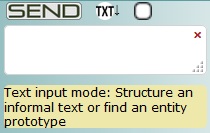 The common interface of the design assistant has the following elements: The common interface of the design assistant has the following elements:
- SEND button: Once the desired text or graphic input is ready to be
processed the user must press the SEND button to pass the data to the
design assistant in order to be analyzed. While the input is in progress
the SEND button changes to a STOP button allowing to cancel the
process.
- Input mode selector button: The mode can be
 for text inputs or for text inputs or  for graphic inputs. When graphic input mode is active the sketch interpreter window is shown at the right. for graphic inputs. When graphic input mode is active the sketch interpreter window is shown at the right.
- Clear message stack button: It can be used to delete all the messages returned by the assistant in past processes.
- Text input area: The user can type here the text to be processed in text input mode.
- Suggestion area: It is an area used by the assistant to show a short message with a hint or suggestion.
|
Just below the suggestion area it is placed the message stack where the
design assistant stores its responses. It is empty at the beginning and
new responses are placed at the top of the stack.
The current version of the design assistant only works on the client
machine so the SEND button does not really send information to a remote
server. That client-server working mode is foreseen for a future version.
|
Working with texts
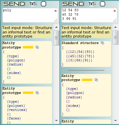 The design assistant in text input mode can be used to find LAI4D entity
prototypes whose type or member names approximately match the words
entered in the text input area. The design assistant in text input mode can be used to find LAI4D entity
prototypes whose type or member names approximately match the words
entered in the text input area.
In the sample image the user typed the word "poly". When the SEND button
is pressed the assistant searches for approximated matches of the
entered words in the internal catalog of entity prototypes. Each
resulting match is displayed as a response in the message stack. The
responses are sorted so as the most relevant one is placed at the top of the stack.
In a similar way the design assistant can also be used to provide Gosyx
format to an unstructured text. In the sample image the user typed a set
of coordinates separated by spaces and distributed in lines, although
other separators or distributions could have been used. When the
SEND button is pressed the assistant tries to recognize a data structure
in the passed text. It implements several generic parsing rules for
identifying the data pieces and their hierarchical organization. This
means that the assistant is able to understand different syntax which, in
return, allows a great flexibility in the input.
This function is very useful for generating the source code of an entity
when the coordinates are to be manually typed or pasted from another
format which uses a different syntax for structuring the data.
All text responses have a "Copy to clipboard" ⧉
button at the right side of the response's header. Once copied, the
response can be pasted into the source editor or a field of the Tree
explorer.
|
Working with sketches
The design assistant in graphic input mode can
be used to interpret a sketch extracting a geometric entity. When the
input mode selector button changes to graphic mode the "Sketch
interpreter" tool is shown.
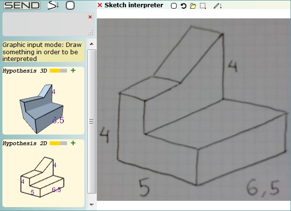 It is a minimalist drawing tool that allows
to paint freehand strokes or to load a picture in the sketch area. Its
UI has the following elements: It is a minimalist drawing tool that allows
to paint freehand strokes or to load a picture in the sketch area. Its
UI has the following elements:
- Clear the sketch area.
- Undo the last drawing step, either a pencil or an eraser movement.
-
Open a file picker dialog to load a picture in the sketch area. A
picture can also be loaded through a drag & drop operation.
 Define a constrain window for the sketch analysis. Define a constrain window for the sketch analysis.- Selector button for choosing between pencil or eraser .
|
The sketch interpreter of the design assistant is the face of the
conceptualizer program JAIC.
The goal of this program is to "imagine"
the conceptual geometry represented by an imprecise raster image in a
probabilistic way regardless of whether it is a recognizable shape or
not. When analyzing an image, the objective of Jaic is to generate a
formal geometry with "sense", either 2D or 3D, ready to be inserted as a
LAI4D entity in the main drawing. "Sense" essentially means that
Jaic tries to detect geometric concepts or some kind of regularity in
the given image. When
enough "sense" has been found Jaic generates a geometric hypothesis.
In the sample image the user hand-drew the
perspective of a shape in a paper sheet and then scanned it uploading
the resulting picture to the sketch interpreter. When the SEND button
is pressed the assistant analyzes the image of the sketch area and
returns a set of hypothesis sorted by relevance in the message stack. By pressing the button  the geometric entity of the corresponding hypothesis is passed to the
design space. The design assistant tries to find the evident reference system of the 3D hypotheses but
the insertion point of the entity is arbitrary. When the drawing is
empty the program automatically performs a zoom extent so the just
passed entity is immediately focused. In other case the user should
manually find the entity.
the geometric entity of the corresponding hypothesis is passed to the
design space. The design assistant tries to find the evident reference system of the 3D hypotheses but
the insertion point of the entity is arbitrary. When the drawing is
empty the program automatically performs a zoom extent so the just
passed entity is immediately focused. In other case the user should
manually find the entity.
The input can be provided either by drawing a sketch
directly
with the sketch tool or by uploading a picture. But it must be clear
that Jaic works with
pixels, not strokes, regardless of whether the input comes from the
sketch tool or from a picture. The sketch tool only paints black strokes
over a white background although Jaic is capable of analyzing colors.
Sharp images
with not too small details, with homogeneous backgrounds and good
contrast between strokes and background are better interpreted by
Jaic. The program doesn't have a preference for a specific kind of 3D
projection but, as it happens to humans, some projections offer more
information about the represented geometry than others and, therefore,
are easier to interpret.
|
The analysis carried out by Jaic could be described as an artificial
imagination process since it begins with a single static image,
normally representing an imprecise hand-made drawing, and without
stereoscopic pictures, depth sensors or motion tracking to help in the analysis. Such a process
can lead to more than one hypothesis, some of them 2D, others 3D, some
of them very similar to that expected by the user, others too different.
The user is in charge of selecting the best hypothesis, if any, for his
purposes. See also the section "Design assistant options".
About the current version of JAIC
This version of Jaic is still very limited and only understands
simple 2D or 3D polyhedral geometries not involving curves. If the user
wants it, measures can be painted in the sketch in order to obtain
geometries with specific dimensions. If no measures are provided (or
recognized) then Jaic sizes the
geometry according to the proportions extracted from the own sketch.
Furthermore Jaic can speculate about hidden faces in some cases. These
functions can be enabled or disabled from the configurations available
at the section "Design assistant options". Not all functions are enabled by default.
Jaic implements a light OCR (Optical Character Recognition)
specifically designed for recognizing numbers painted in the sketch.
These numbers are intended to be measures of segments and can have
decimal separators. Once recognized Jaic tries to link the measure to
the painted segments basing the decision on proximity. If the linking is
not possible then the measure is discarded. It is not necessary that
all geometric elements have a measure. With the final set of geometries
and measures Jaic tries to conveniently resize the different elements of
the shape obtaining an hypothesis.
The success of the resizing depends on many factors and it is possible
that only some of the measures get finally assigned to the corresponding
geometry. 2D and 3D hypothesis are resolved using different algorithms
and have different conditioning so the set of assigned measures may also
be different. Indeed the provided set of measures can be compatible
with 3D shapes and not with the corresponding 2D projection. For
example, imagine the sketch of a regular tetrahedron in which the user
paints the 6 measures for the 6 segments of the tetrahedron; it is
obvious that the given set of measures is only compatible with the 3D
hypothesis and not with the 2D one. It is also possible to provide
measures geometrically incompatible as for example giving the lengths
10, 4, 3 to the segments of a triangle. In such cases some of the
measures are automatically discarded by Jaic.
To increase the probability of success in the use of the sketch interpreter follow these hints:
- Simple and sharp images are interpreted faster and the geometries are better conceptualized by Jaic.
- A good contrast between the ink and paper will facilitate the extraction of the drawing elements.
- Avoid too big gaps when sketching lines.
- If a scanned picture presents sheet borders or graphic traces not
related to the sketch then use a constrain window to restrict the
analysis area.
- Avoid sketching partially hidden faces. Jaic is still unable to handle them and will only cause problems.
- If numbers are used then try to paint them clearly, the implemented OCR has its limits.
- The numbers must be horizontal and the digits composing a number should have similar size.
- Avoid too big or too small numbers. The height of a number must
not be greater than 1/3 of the biggest side of the bounding-box of the
sketch. In other case Jaic will consider it a geometric element instead
of a number.
- The number must be close to the segment it is to be linked to, but
not in direct contact, preferably with a separation of at least 1/2 the
height of the number.
- It is preferable for the proportions between painted segments
to be coherent with the painted measures. This is particularly
convenient for the elements without assigned measure.
- Usually it is not necessary to provide all measures in a sketch, for
example, two measures are enough for a rectangle. With more complex
sketches try to concentrate all the provided measures in highly
connected elements in order to facilitate the analysis.
The general features are explained through the next examples. The
pictures shown as input can be used for testing purposes. Some of them
have been drawn with the sketch tool and others have been scanned from a
paper sheet. The analysis of raster images can be affected by the
browser's zoom:
Input
|
Output
| Comments
|
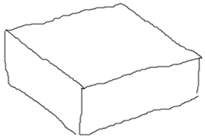
|
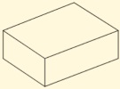 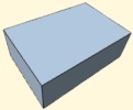
| A simple, clear and sharp image. In this case both 2D and 3D hypotheses have a clear sense.
|
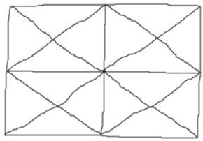
|
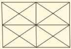 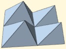
|
Jaic is good understanding tabular
layouts, but many different connections between points may difficult
the perfect alignment of segments.
|
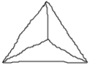
|
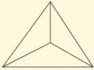 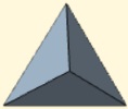
|
By default Jaic imagines the vertex of a pyramid closer to the observer than the base, as humans usually do.
|
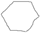
|
|
In general, regular polygons are
easily detected in 3D hypothesis. As opposed to 2D hypothesis that work
with segments, 3D hypothesis work with faces which allows other
topological analysis.
|
|
 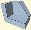
|
Another example of how clean sketches of simple geometries are well conceptualized by Jaic.
|
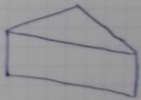
|
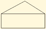 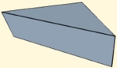
|
The good contrast between ink and paper makes the scanned picture acceptable for analysis.
Jaic tries to give sense to the 3D hypothesis using the available information.
|
|
 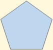
|
In this case the 3D hypothesis returned a regular pentagon, but poor sketches or blurred pictures are difficult to interpret.
|
|
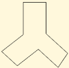 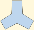
|
Despite the poor quality of the
sketch, Jaic understood it as a cyclic geometry. This analysis is
performed only for 3D hypotheses.
|
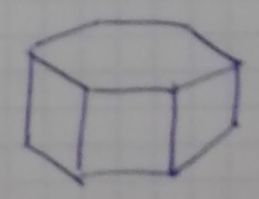
|
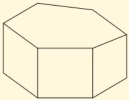 
|
Jaic correctly understood that the base of the prism was a regular hexagon.
The poor image quality hindered the generation of a 2D hypothesis with
more sense and this, in return, could lead to useless 3D hypothesis.
|
|
|
This geometry is still simple enough
to be conceptualized although resulting proportions between shape
elements are not what they seem in the picture.
|
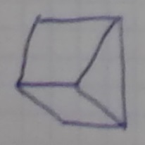
|
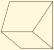 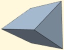
|
Despite the low quality of the image the 3D hypothesis returned by Jaic has a lot of sense.
|
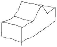
|
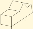 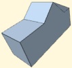
|
The geometry is reasonably well interpreted but for the partially hidden face.
Jaic does not implement knowledge to handle hidden faces yet.
|
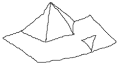
|
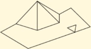 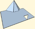
|
Jaic did what it could with this abstract geometry.
|
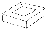
|
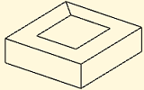 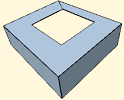
|
In this version the holes of a face
must be connected to the external face contour, either directly or
through another hole already connected. Faces with holes can be handled this way.
|
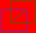
|
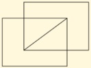 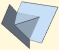
|
This is an example of how Jaic can work with colors.
If this picture were edited and converted to grey scale it would become into a grey rectangle.
|
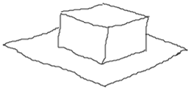
|
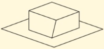 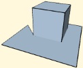
|
Although the provided sketch is reasonably clear, the partially hidden face remains broken.
|
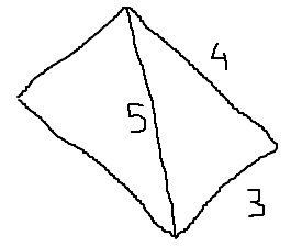
|
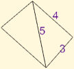 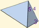
|
Jaic tries to preserve the proportions of the provided segments when they don't have assigned measures.
|
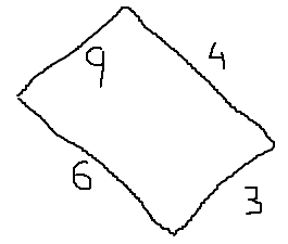
|
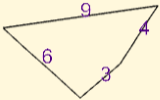 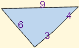
|
With those measures the orientation of segments cannot be preserved.
|
|
|
The measures were correctly
understood but they only have sense for a 3D hypothesis. Indeed the 2D
hypothesis shows one of the tetrahedron's sides, not its base.
|
|
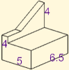 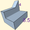
|
Jaic accepts decimal separators
placed at the bottom or at the top of the number. The size of a
separator should not be greater than half of the number's height.
All numbers were correctly recognized but the perspective of the 3D hypothesis hides two of them.
|
Errors and problems
LAI4D manages an internal list of raised
errors and warnings all of them referred with the common name of issues.
The user can inspect that list at any moment by pressing the "Issues"
button placed at the bottom-right corner group of on screen controls
(only if the list has issues). Each time the drawing source is updated
the list of issues is cleared and any new error occurred during that
process is registered and notified. The messages are intended to be self-explaining allowing to identify
the cause of the problem. In design mode, the error message is
accompanied of an error trace summary intended to facilitate the
investigation of the issue by the LAI4D development team when the cause
is not clear. LAI4D implements the error handling strategy
of the Iquix framework. This strategy focuses attention on generating
useful information of unexpected exceptions as well as on providing
additional tools intended to help in the investigation of difficult
problems. Some of the configurations and utilities of this strategy can be found in the section "Iquix administration".
Most of error messages raised by LAI4D are related to the interpretation
of the drawing source or the start-up instructions. It is also possible
to detect problems which do not raise errors such as for example
missing entities in the drawing or unexpected colors. Some LAI4D
functions do not work while offline or when the HTML page has
been loaded from a local drive instead of from the Internet; this is a
browser limitation and not all browsers present the same restrictions.
The user shall remember that the canvas 2D rendering context does not
offer
exactly the same characteristics as the WebGL rendering context and
this is not an error but a limitation. See the "2D and 3D graphics"
section for more details.
These are the most common causes of errors and problems:
- Incorrect use or number of curly brackets when the source is
manually edited. Nodes incorrectly closed or opened usually causes
parsing errors.
- Entities with undeclared mandatory members.
- Incorrect order or number of child elements in compound elements of entity definitions.
- Entity members whose value should be a container but is
established as continent. A typical mistake could be to set the value of
a "folder" member as an entity instead of a collection of entities.
Furthermore this mistake will probably not raise an error because the
interpreter simply considers that the folder has no entities.
- Incorrect use of inheritance. Referenced names not found;
inherited members that should not be inherited; unexpected combination
of transformation members; the casuistic of this kind of problems is
wide and normally no errors are raised.
- Unknown entity types or incorrect member names. Typing "face"
instead of "faces", or trailing spaces in the name can cause this error.
- Unexpected value types.
- Problems loading image files when a polynet defines a "signal
image", or loading drawing sources from a remote server. Sometimes it can be
a simple error in the file path. But it can also be a cross domain
restriction, problems of the asynchronous communication or a limitation of the browser when working offline.
Graphic
accelerated hardware is a limited resource and web browsers limit the
number of WebGL contexts that can be simultaneously working. When the
number of canvas elements using WebGL surpasses that limit, the web
browser automatically losses the WebGL contexts of the oldest ones. This
results in the disappearance of the graphic rendered in those canvas
elements. In order to recover it use
the "Repaint" function of the corresponding LAI4D widget.
In very rare situations the widget may enter into an
unstable or erratic behavior. Sometimes this problem can be solved using
the "Repaint" function. Although less probable, it is also possible to suffer other kinds of
errors that have nothing to do with the topics previously mentioned. These are
unexpected exceptions which indicate some bug in the application code,
or even in the web browser, and should be notified to the LAI4D development team.
Web browsers internally implement a security control to prevent long JavaScript executions from freezing
the browser. When working with large drawings it is possible to get an
alert message raised by the web browser warning the user about this
situation and asking whether to stop the script or not. If this happens
the normal choice is to continue with the execution until the process
ends, unless it is clearly caused by an error. If the script is finally
stopped then it is recommended to reload the page. The rendering of
algorithmic entities executing long loops could also lead to this
situation.
When designing large or complex
drawings it is highly recommended to make temporary copies of the work
from time to time. This can be easily done with the function "Browser's
storage".
|
In case you want to report a problem please visit the "community" section of the LAI4D's official website at www.lai4d.org.
Publishing LAI4D drawings
To share a LAI4D drawing can be as simple as
sending a link generated with the "Share" button. But the user could
face other publishing scenarios such as sharing large drawings or
generating HTML documents with embedded drawings in which a better
knowledge of the involved processes is recommended.
Widget initialization
This section explains how to provide the
initial configuration and the initial drawing source for a LAI4D widget. This
initializing data is called the start-up instructions
and to know how to handle them is important for sharing or publishing a
LAI4D drawing. The start-up instructions are currently provided through
the URL data (a.k.a. URL query srting)
that is the last part of the URL after the path of the
HTML file. If no start-up instructions are provided then a default configuration is
used and an empty drawing is shown. The following data items can be
specified in the start-up instructions although none of them is
mandatory:
- The drawing source: If not specified then an empty drawing is shown. There are several options for indicating this item.
- The initial view configuration: If not specified then the default view defined by the loaded drawing, if any, will be used.
- The widget size: Is a pair of values with the width and height
of the rectangular window area expressed in pixels that the widget
should occupy. If not provided then all the window available area is
occupied. This instruction is only considered in reader mode. Indicating
the size of the widget in the start-up instructions is rarely necessary
because, when the widget is embedded in an IFRAME element is this
element in charge of specifying the size, and when the widget is
displayed in a dedicated web page the size is not important.
- Different widget behaviors such as those related to the initial arrangement of the "on screen controls".
- The non-standard functionality to be loaded into the widget: The
look and behavior of the LAI4D widget can be changed in order to add new
functions for specific types of designs or according to customer
requirements.
The start-up instructions are encapsulated in a data structure codified
as a Gosyx entity. See the "Lai4dCL" section for more details about
Gosyx entities. This initializing entity can have the following optional
members:
- source: Is directly the
drawing source. The value of the member contains one or more LAI4D
entities. It can be a canonical or a non-canonical source as explained
in the section "Edit source". It must be clear that the value of this member is not an entity but a container of entities.
- file: Its value indicates where to find the drawing source. This value can be simple or compound:
- If simple then it is considered a string with the URL of a text
file from which to retrieve the drawing
source and works in the same way as the URL of
any other HTML resource such as images or CSS style sheets. The URL can
point to any domain and can
be any of the types accepted by the browser such as "http" or
"ftp". Relative URLs are relative with respect the LAI4D
HTML file. LAI4D drawings are stored by default UTF8 encoded with the
".L4D" file extension but the real file extension used is not relevant.
- If compound then it contains the necessary information for
retrieving a drawing source from a hosting system that requires a specific
communication protocol (a remote server for instance). The first element identifies the option and
these are the available possibilities:
- lai4d: The file is retrieved from the LAI4D server requiring
only the desired file name. The value node of this "file" member has the
prototype
{{lai4d}{file name}}. The file should have been
previously saved with the function "Save server file". This option only
works when the LAI4D widget has been loaded directly from the LAI4D
official site.
- browser: The drawing source is retrieved from the browser's storage
requiring the corresponding item key. The value node of this "file"
member has the
prototype
{{browser}{item key}}. This option is intended
for loading dynamically generated drawing sources through JavaScript in
licensed LAI4D custom modules and it is disabled in the current version
of the standard LAI4D widget.
- view: The value of this
member is a "view" entity that will be passed to the "view" member of
the drawing entity (replacing any previous value) so it will become the
initial view configuration.
- append: The value of this
member contains one or more LAI4D
entities that are going to be appended to the "folder" member of the
main drawing before it is interpreted. The "append" member is intended
to let the user to modify the drawing source from the URL start-up
instructions. Possible usages of the "append" member could be to include
customized entities or to add a named entity which will be
inherited by others. It must be clear that the value of this member is
not an entity but a container of entities.
- size: Is a pair of
values with the width and height of the LAI4D widget in pixels. If the
indicated size is greater than the available window area then scroll
bars will be shown.
- flags: This member is
intended to contain a set of keywords whose
mere presence indicates a configuration to be used when the widget is
loaded. It works both in reader and design modes but it has no practical
use in the last one. If the concurrency of several flags generates a
conflict then
the following flag order is used as a priority selector.
These are the currently supported keywords and their meaning:
- controls fixed: The "on screen controls" are always shown.
- controls hidden: The "on screen controls" are always hidden.
- camera fixed: The camera configuration cannot be modified through screen events.
- modules: Its value
identifies the non-standard functionality that must be loaded into the
widget. This option is intended for loading licensed LAI4D custom
modules.
In the strange case that more than one member for retrieving the
drawing source is provided, the priority order is: source, file. As any
other Gosyx structure, the initializing entity is parsed and this
process could generate errors if it is badly written. The "Share"
function is the easiest way for generating the URL with the main start-up instructions.
Here is an example of a complete URL with start-up instructions. In this
case the LAI4D widget is in reader mode. The "size" member is provided.
The "source" member indicates a canonical drawing source because it
directly contains a drawing entity. Note that the value of the "source"
member is not a drawing entity but a container that has a drawing
entity:
http://widget.lai4d.org/lai4d_viewer.html?{{size}{{300}{200}}{source}{{{type}{drawing}{folder}{{{type}{sphere}{radius}{100}}{{type}{box}{diagonal}{{50}{100}{50}}{translate}{{100}{0}{0}}}}}}}
In this other URL sample the LAI4D widget is in design mode. The "size"
member is not provided and it would have been ignored anyway because of the design mode. In this
case the "source" member indicates a non-canonical drawing source since
it contains two graphic entities instead of a drawing entity:
http://widget.lai4d.org/lai4d_designer.html?{{source}{{{type}{sphere}{radius}{100}}{{type}{box}{diagonal}{{50}{100}{50}}{translate}{{100}{0}{0}}}}}
Now this URL results in the same drawing as the previous one, but in
this case the "sphere" entity is added to the drawing using the member
"append" of the start-up instructions instead of through the "source"
member. This is only an example, the combined usage of both "source" and
"append" members in the start-up instructions has no sense:
http://widget.lai4d.org/lai4d_designer.html?{{source}{{{type}{box}{diagonal}{{50}{100}{50}}{translate}{{100}{0}{0}}}}{append}{{{type}{sphere}{radius}{100}}}}
This example uses the member "file" for indicating that the drawing
source is stored in a file named "sample_a25" that must be retrieved
from the LAI4D server. This could be the typical URL of a drawing
intended to be displayed online assuming that the widget is loaded
from the LAI4D official site:
http://widget.lai4d.org/lai4d_viewer.html?{{file}{{lai4d}{sample_a25}}}
In this case the member "file" indicates a remote URL for retrieving the
source. This could be the typical URL of a drawing stored in the
personal web space of the user
intended to be displayed online assuming that the widget is loaded
from the LAI4D official site:
http://widget.lai4d.org/lai4d_viewer.html?{{file}{http://www.mydomain.com/sample_drawing.l4d}}
Now the member "file" indicates a local text file
from
which to retrieve the drawing source (the real file extension is not
relevant but must be indicated in order to find the file); the file is
located in a
directory named "sources" that is a child of the directory containing
the LAI4D HTML file. It also indicates that the on screen controls must
always be hidden. This could be the typical URL of a drawing intended to
be displayed as an embedded IFRAME element in a HTML document prepared
to be consumed not only online but also offline, in which case the
LAI4D HTML page should be part of the document structure:
.../lai4d_viewer.html?{{file}{sources/sample.txt}{flags}{{controls hidden}}}
Suppose we have a file named "algorithm_a25" stored in the LAI4D server
which defines a "program" entity intended to generate a especial
geometry. In return suppose that "program" entity needs to be passed
some arguments through its "variable" member, but it does not define
such a member because it is expected that the user provides it through
the start-up instructions. The "program" entity has a member "inherit"
whose value points to an entity named "arguments" which is not defined
in the original drawing. Then the user can provide the arguments to the
"program" entity using the member "append" in the start-up instructions
in order to append an entity named "arguments" defining the "variable"
member to be inherited. Note that the value of the "append" member is
not an entity but a container of entities. This could be the URL for
that situation:
http://widget.lai4d.org/lai4d_viewer.html?{{file}{{lai4d}{algorithm_a25}}{append}{{{name}{arguments}{variable}{expected
 arguments}}}}
Some servers limit the maximum
length of URLs in order to avoid abuses. Furthermore this limitation can
also be imposed by the web browser. For example IE limits the URL
length to 2048 bytes. This restriction is important when the drawing
source is specified through the "source" member since large drawings can
easily surpass the limit.
The dynamic loading of files can be problematic for a number of reasons.
The simplest cause could be an error in the file path. But it can also
be a cross domain restriction or a limitation of the browser when
working offline.
|
It is pretty obvious that what is going to be rendered in the viewport
depends mainly on the drawing source. Therefore, the designer should
keep attention not only to the start-up instructions but also to the
"drawing" entity configuration, particularly to the members "view",
"background color" and "flags", which directly affect to how the drawing
is initially shown. See also the "Share" and "File" sections.
The Iquix framework provides additional functionality that can also be
activated from the URL data. In LAI4D this possibility is used for
manually
configuring the UI language (the UI language is automatically set by
default to that of the operating system). For example, putting the text
"lang=es&" just after the "?" character and before the start-up
instructions will set the UI language to Spanish. The text piece after
the "=" character must be one of the supported two letter language
codes. If not provided or not recognized, the default UI language is
taken from the browser configuration which, in return, normally takes it
from the operating system. When a suitable translated text cannot be
found then the English version is used. This sample could be a complete
URL
specifying also the desired UI language:
http://widget.lai4d.org/lai4d_viewer.html?lang=es&{{file}{{lai4d}{sample_a25}}}
In case the UI language is going to be manually configured without start-up instructions then an empty start-up instructions ( {}) should be provided. In other case the parser will consider that the start-up instructions are badly formed.
The official URLs for the LAI4D widget are:
http://widget.lai4d.org/lai4d_viewer.html
http://widget.lai4d.org/lai4d_designer.html
Any other URL shall be considered provisional.
|
Sharing drawings online
When a user intends to design and share a drawing online the most comfortable strategy consists of the following steps:
- The user opens the official LAI4D designer web page.
- Then creates the drawing. During the design process the user can
use the "Browser's storage" function to quickly store and retrieve
temporary drawings.
- If the drawing uses "signal image" entities or integrates links
which cannot be retrieved from the Internet then it is recommended to
encapsulate those resources inside the drawing using the utility "Base64
file encoder".
- When the drawing is finished, and if the user considers it
convenient, the "Drawing metadata" function can be used in order to
set in the drawing source the current view definition or the background color. In this way the drawing
will be initially displayed as the designer expects.
- Once the design is finished and ready to be published, the user
saves the drawing using the function "Save server file" in order to
store it in the LAI4D server making it available to the Internet. After
the drawing is saved the server returns back the definitive name
assigned to the drawing file which the user should keep. An URL for
sharing the file is automatically shown too. If the user only needs that
URL for sharing the drawing as a link then the next step is
unnecessary.
- Using the "Share" function the user can generate an URL for
sharing the drawing as a link that can be directly sent to other users,
or as an IFRAME element that can be embedded in HTML documents. By
default the generated URL is exactly the same as that used for loading
the widget, something useful in reader mode. The user
must mark the check box "Use options" and then unmark the
check box "Designer mode" if he wants to share the drawing in reader
mode. The check box "Include file origin if available" should be
already marked.
The URL generated in the last step should look something like:
http://widget.lai4d.org/lai4d_viewer.html?{{file}{{lai4d}{just_saved_file_name}}}
If the user has his own web space then to save the file to the LAI4D
server is not necessary. The user can save the drawing source in a text
file stored in his web space and then reference it using its absolute
URL in the following way:
http://widget.lai4d.org/lai4d_viewer.html?{{file}{http://www.mydomain.com/sample_drawing.l4d}}
Drawings in offline documents
LAI4D can be used not only online but also offline. The LAI4D web page
downloaded from the Internet can be saved to a
local drive of the client machine using the standard "Save as"
function of the web browser normally located in the "File" menu. This
will allow the user to work offline regardless of whether the LAI4D page has been
cached or not by the browser. This is particularly necessary if the user
wants to create a distributable HTML document containing embedded
LAI4D drawings as IFRAME elements that can be displayed both online from
the Internet or offline from the local drive of a computer. The
suggested steps for creating such a document are:
- Create a main folder in the local drive intended to contain all the structure and resources of the document.
- Inside the main folder create another folder for the LAI4D resources.
- Use
the web browser to connect to the latest version of the LAI4D viewer
page at the LAI4D's official site. Then save it to the just
created LAI4D folder
using the "Save as" function of the web browser (use the 'complete
HTML page' option to download all the resources). After this the LAI4D
folder will usually contain the main LAI4D HTML page and a new folder
with icons, CSS style sheets and JavaScript files. Check that the saved
LAI4D HTML opens normally with the browser offline.
- Inside the main folder create a new folder and place there all
the source files of the LAI4D drawings that will be shown in the
document.
- Create the HTML document with the desired layout and the desired non-LAI4D content and place it inside the main folder.
- Insert the necessary IFRAME elements (one for each drawing) in the HTML document. For each IFRAME:
- Configure the desired size through the attributes "width" and "height".
- Set the style properties "margin" to 0, "border" to 0, "overflow" to "hidden".
- Configure the "src" attribute with a relative URL pointing to the
saved
LAI4D HTML file and with the start-up instructions indicating the
corresponding drawing source file. It is not necessary to indicate the
widget size in the start-up instructions since the widget will occupy
the whole IFRAME area. See the "Widget initialization"
section for more details. The "Share" function can also be useful.
- The source code of the IFRAME element should look something like:
<iframe
src="lai4d/lai4d_viewer.html?{{file}{../drawing_sources/sample.l4d}}"
 style="margin: 0; border: 0; overflow: hidden;" height="200"
width="300"></iframe>
. Note that the path of the drawing source must be relative to the LAI4D HTML page.
- The HTML document is ready. It can be distributed as
normal computer files (a zip file with all the resources for instance)
or it can be published (uploaded to a web server) in order to make it
readable online. The users reading the document online will be able to
save it to their computers using the standard "Save as" function of
their browsers.
As previously mentioned, some browsers restrict certain functionalities
(particularly local file access) while offline.
LAI4D architecture
LAI4D has been implemented as a web
application so it is composed of a HTML file, several JavaScript files,
a CSS style sheet and some other resources like image icons for
instance. Since most of its functionality is based on vector graphics
LAI4D exploits the canvas HTML element. This means that it should be
executed in a HTML5 compatible web browser, what is not a problem
because all major browsers support HTML5.
LAI4D has been built over the Iquix framework. Iquix is a proprietary
JavaScript library that ranges 3D vector graphics, computational
geometry, physical simulation, artificial intelligence, multi-thread execution as well as other
more conventional functionalities. When the development of Iquix begun it was still important
to provide compatibility for browsers like IE6 or Mozilla running on Windows XP,
which were not so old browsers at that moment. Iquix still preserves a lot of
polyfills and compatibility functions for old browsers but this strategy
has been considered obsolete and it is being removed so the use of a
modern browser is recommended.
New web standards have supposed a great impulse to the development of
web applications but some limitations still exist. Not all web browsers
have the same behavior, same capacities or the same degree of compliance
with standards. Security constraints limit the programmatic access to
local files on the client machine. The
multithread execution API is not completely stabilized and is
uncomfortable and incomplete due to the not shared memory approach used.
Browser capabilities may be different depending on whether the
application has been downloaded from the Internet or from a local drive
in the client machine.
If the user intends to work with LAI4D offline
then some browsers require special configuration tricks for
enabling certain capabilities while offline. Theoretically a cached HTML page should work offline much the same as online.
This section tries to offer a better understanding of the software scope and to clarify some aspects of the same.
Working modes
LAI4D can be essentially used in two ways or modes:
- Reader mode: This mode is used to explore a 3D design changing the
camera configuration and for querying information from the drawing like
point coordinates, distances, user custom data, etc.
- Design mode: This mode is an extended version of the reader
mode and allows the user to create or modify a 3D drawing through the
following main methods:
- Source edition: The drawing source is a set of entities
described in the canonical language Lai4dCL that can be handled as plain text.
This would be the preferred method for users not willing to invest time
on learning how to work with the command and graphic interface because
they only need to handle basic shapes and are going to make an
occasional use of the tool.
- Command and graphic interface: In a
similar way to that exposed by other conventional CAD tools, LAI4D also
offers a set of
functionalities which can be accessed by means of a command menu or
selecting points and entities on the screen. Operations such as copy,
move or rotate can be performed in a more comfortable manner using
this kind of interface than using the source editor. The usage of the
command and graphic interface, although clearly powerful, demands to the
user an effort for learning several work-paths in order to achieve
results in a comfortable and productive way. This is the reason because
of the direct source edition can be better for inexperienced and
occasional users.
- Design assistant: The simplest way to
exploit a design tool is to find an expert that knows how
to handle the tool and that simultaneously understands what the user
wants to design. To develop a
design assistant with such capabilities is the initial and main
purpose of LAI4D. This technology is absolutely experimental and is at a
very early stage of development. The first versions will be mostly
focused on sketch conceptualization and computer vision techniques.
Both working modes can be used not only online but also offline.
See the "Publishing LAI4D drawings" section for more details. The
LAI4D widget in reader mode (LAI4D viewer) will be usually found embedded in other web
pages as an IFRAME element whose URL indicates both the location of the
LAI4D HTML file and the drawing source. Obviously the LAI4D widget can
also be displayed in a dedicated web page, which is the normal situation
for design mode (LAI4D designer).
See the "Start-up process" section for more details.
Storage and retrieval of drawing sources
In a desktop application the concepts of
storage and retrieval are normally reduced to save or open a file in the
machine's file system. However, in a web application the options
related to storage and retrieval are wider. These options can be
categorized according to the working scenario:
- Usage of the URL as container of the source: The string typed in
the address bar of the web browser not only indicates the path of the
navigated web page but also can include additional information such as
the data source.
- Sources stored in the cloud: Remote servers hosting files or
other web services can be requested to save or return a drawing source
requiring some specific protocol.
- Local source files: In certain conditions a web application can
also access files stored locally in the user's machine much the same as a
desktop application does.
- Internal browser storage: Modern browsers are able to internally
store in a persistent manner relatively large data packages that can be
handled as files.
LAI4D exploits several strategies and web technologies for managing
drawing sources because, depending on the user's intentions, some of them
can be better than others. Since facilitating the sharing of designs is
also an objective of the project, one of those options is the possibility of
freely storing and retrieving drawing
sources in the LAI4D server being this feature the easiest way for
publishing LAI4D drawings on the Internet. But the user can also use another web space for this purpose.
In a similar way,
those options
can be classified according to where the data resides in the following
groups:
- URL: The last part of the URL contains the start-up instructions
which can indicate directly the drawing source or where to retrieve it from.
See the "Widget initialization" and "Share" sections for more details.
- Server: The files are stored in a remote server and are publicly
available on the Internet to any user having the file name in a
read-only way. Particularly useful for sharing purposes. See the "Open
server file" and "Save server file" sections for more details.
- Local: The files are stored in a local drive of the user's
machine. See the "Open local file" and "Save local file" sections for more details.
- Browser: The files are stored internally in the own browser.
Particularly useful for managing temporary drawings during the design
work. See the "Browser's storage" section for more details.
Unfortunately some of the features intended to manage drawing
sources in
the own client machine may not work when the application
runs
offline and different browsers offer different capacities. Regarding the remote drawing sources, the user should
be aware that, depending on the situation, difficulties may arise due
to security restrictions. The good news for all users is that,
regardless of the working scenario or any possible problem with the storage
or retrieval functions, the LAI4D widget (reader or designer) always
allows to inspect and copy the current drawing source as plain text; and
in return the LAI4D designer widget always allows to set and edit the
current drawing source as plain text.
The available LAI4D functions related to storage and retrieval can be
analyzed in the sections "Share", "File" and "Publishing LAI4D
drawings".
2D and 3D graphics
Regarding vector graphic capabilities, HTML5
offers two main approaches through the use of the canvas element, both
covered by Iquix:
- The canvas 2D rendering context that allows to draw 2D
geometries. 3D geometries can be painted only if they are previously
projected using a convenient library like that found in the Iquix framework.
- The WebGL rendering context, which is also essentially a 2D
drawing API but with the big difference that it exploits the graphics
acceleration hardware present in the platform expressly designed to process at a
high speed large amounts of 3D geometric data. This API again demands a
special program for processing the 3D geometry in order to render it, a
program that can also be provided by the Iquix framework.
Since both rendering contexts have different capabilities
and
the Iquix framework have different functions for handling them, the
LAI4D interpreter acts as an abstraction layer trying to achieve a good
degree of convergence in the drawing rendering process regardless of the
rendering context used. In general the use of WebGL results in a better
graphic quality and
experience but unfortunately not all devices are WebGL enabled despite
the web browsers do are compatible. LAI4D automatically detects the
availability of WebGL and tries to use it if possible. If WebGL is not
available then LAI4D will use the canvas 2D instead. This 2D rendering
context, while offering a reasonably good experience, has some
weaknesses:
- Complex drawings render slowly because the accelerated graphics
hardware is not available. From a mathematical point of view, the
necessary calculations for obtaining the projection of the 3D geometry
are similar in both contexts, but in the canvas 2D context all those
calculations must be performed by the main microprocessor which is not
specialized in such calculations.
- The hiding of far objects by
closer objects is imperfect. The
perfect calculation of object hiding, while mathematically possible, is a
process so heavy that it has to be replaced by a lighter algorithm
based
on calculating the painting order of the objects. To detect failures of
object hiding is very easy even in not complex drawings. WebGL
implements a more immediate and suitable strategy since hiding is
computed pixel by pixel according to depth.
- Curved
surfaces appear as polyhedrons because the calculation of curved
surface brightness is too onerous, although not impossible. For the same
reason polyhedrons are to be painted with a single color per face,
while in WebGL they can define a color per vertex obtaining an
interpolated face coloring.
Apart from the typical linear and surface geometries, LAI4D also handles
signals. Signals are 2D graphic entities that are always painted
parallel to the projection plane regardless of the camera orientation,
although they have a 3D position and are scaled according to depth when
rendered in perspective projections. They can be images, texts, circular
dots and polygons. WebGL does not offer a means for generating texts so
they are created in an auxiliary canvas 2D context and passed to the
WebGL context as an image.
LAI4D supports RGBA colors, it is to say, colors with partial opacity or
transparency. The projection engine of LAI4D does not perform
photo-realistic rendering so the use of transparencies may lead to
unrealistic results. Line widths are represented normally in canvas 2D
contexts, but not all
WebGL implementations consider line widths different from 1 pixel so
graphic entities may be rendered ignoring line width specifications in
WebGL rendering contexts.
To develop a standard CAD application with its conventional interface
is
not a priority of LAI4D. Indeed the implemented design tool has been
developed with the idea of offering those functions that are less common
in commercial CAD systems, but preserving a good degree of simplicity
for inexperienced users. Therefore LAI4D does not try to imitate the
structure or behavior of other professional design applications although
more and more functionality can be added as the project progresses. The
following is a non-exhaustive list of graphic functionalities that are not
currently a priority for the project:
- Photo-realistic rendering.
- Usage of materials and textures.
- Advanced control of lighting.
OCR
The sketch interpreter implements Optical
Character Recognition functionality intended to allow the assignment of
measures to the generated hypothesis. It is specifically designed for
recognizing numbers and completely runs on the client machine. This OCR
is essentially based on a single layer convolutional neural network
which allows a fast execution with a reasonable success rate.
Server side functions
The current version of LAI4D runs all the CAD
and design assistant functionality on the client machine. This means
that no information is sent to a remote server during the working
process. This is also true for the "SEND" button of the design
assistant. The "SEND" name is foreseen for the future when the heavy
algorithms of the design assistant will need high performance computing.
By now LAI4D is essentially an HTML5 application that can be executed
offline.
Only the following functions depend on server side capabilities:
- Storage and retrieval of drawing files on the LAI4D server.
- Retrieval of drawing files from Internet locations using absolute URLs.
Start-up process
When the LAI4D HTML file is loaded in the web
browser all the necessary resources like JavaScript files, CSS style
sheets or image icons are also loaded. Although the LAI4D designer is an
extension of the LAI4D viewer there are two different HTML
files for them because the designer
needs several resources unnecessary for the viewer. Once the
resources are loaded the start-up process can be divided into the
following steps:
- If URL data has been provided then LAI4D reads it looking for
start-up instructions.
The URL data is the last part (query string) of the URL after the path of the
HTML file. Some widget configurations and the drawing source can be
specified in the URL data. Additionally the start-up instructions could
indicate the non-standard functionality that should be loaded into the
widget. In this step it is also possible to configure a custom UI language that is
taken from the browser configuration by default.
- The widget components are created and the layout is sized
trying
to fill the available window area. It is possible to indicate the widget
size through the URL data. In reader mode the viewport occupies all the
window area. In design mode a new component intended to show the
design assistant is placed at the left or at the bottom of the
viewport component depending on the window dimensions; additionally the
page will have a header and a footer; the widget will have a minimum
dimensions of 600×400 in landscape configuration or 400×600 in portrait
configuration.
- The LAI4D widget tries to retrieve the drawing source according to
the start-up instructions indicated in the URL data if any. If no source is
provided then an empty drawing is shown.
- The drawing source is interpreted in order to translate the entities
described into geometric information that can be rendered. Most
of the possible LAI4D errors are reported in this step due to syntactic
errors or fails in the structure of entities.
- LAI4D selects one rendering context according to the browser
capabilities (WebGL if possible) and then renders the geometric
information resulting from the interpretation step displaying the
drawing in the viewport.
Any error raised will be notified in a report of issues. See the
"Issues" section for more details. The usage of the URL data for giving
the initial configuration to the widget is explained in the section "Widget initialization".
Notes
The LAI4D's official website at www.lai4d.org offers the following contents and additional information:
- The documentation directory with manuals and tutorials.
- A selection of didactic samples.
- The community where users and developers can discuss enhancement proposals, post questions, share works or report errors.
- Copyright notices and terms of service.
© 2016-2025 Lai4d Systems
|
|


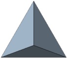
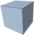
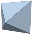
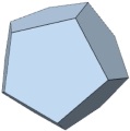
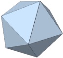
 Orbital: The camera can be rotated around the target point. This
mode allows to explore the entity located at the target point from
different points of view.
Orbital: The camera can be rotated around the target point. This
mode allows to explore the entity located at the target point from
different points of view. Polar:
The camera can be rotated around the view point. This mode allows to
point the camera towards any part of the scene.
Polar:
The camera can be rotated around the view point. This mode allows to
point the camera towards any part of the scene. ) allows to inspect the parent node of the currently shown node. The
component does not retain the inspected element when it is hidden. Note
that any node of the tree can be inspected in two different ways
touching in the icon button just at the left of the node representation:
) allows to inspect the parent node of the currently shown node. The
component does not retain the inspected element when it is hidden. Note
that any node of the tree can be inspected in two different ways
touching in the icon button just at the left of the node representation: As a simple value (for single nodes) or as an expandable tree view
(for compound nodes). This is the default inspection mode. When this is
the active mode additional buttons are shown at the right of the node
representation:
As a simple value (for single nodes) or as an expandable tree view
(for compound nodes). This is the default inspection mode. When this is
the active mode additional buttons are shown at the right of the node
representation: Insert before: Inserts a new node just before the current one modifying the list of child nodes of the parent node.